Production method for plasma display panel

a production method and plasma technology, applied in the manufacture of cold cathode, electric discharge tube/lamp, electromechanical system, etc., can solve the problems of degrading performance, affecting the quality of plasma, so as to achieve excellent display performance and good quality

Inactive Publication Date: 2006-07-04
PANASONIC CORP
View PDF16 Cites 13 Cited by
  • Summary
  • Abstract
  • Description
  • Claims
  • Application Information

AI Technical Summary

Benefits of technology

[0024]This manufacturing apparatus enables the above manufacturing method to be realized. Accordingly, a PDP that includes ...

Problems solved by technology

The problem is, however, that magnesium oxide possesses the property of absorbing water, and has the property of altering when containing water.
Therefore, if the protective layer made of magnesium oxide comes in contact with an atmosphere containing a predetermined amount or more of water vapor, its performances may be degraded.
Als...

Method used


Image

  • Production method for plasma display panel
  • Production method for plasma display panel
  • Production method for plasma display panel

Examples


first embodiment

1. First Embodiment

1.1 Construction of the PDP

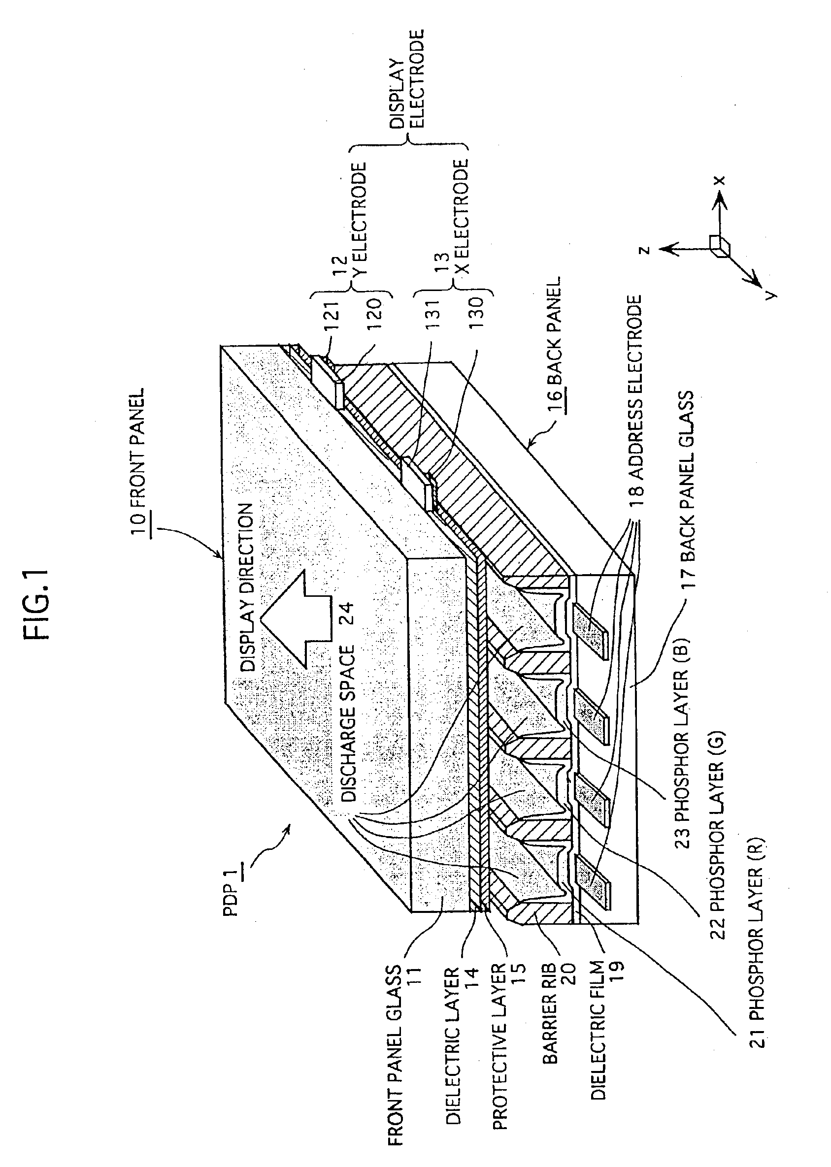
[0031]FIG. 1 is a sectional perspective view showing the essential components of an alternating current (AC) surface discharge type plasma display panel 1 relating to the first embodiment (hereafter simply referred to as “PDP 1”). In the figure, the direction z corresponds to the thickness direction of the PDP 1, and the plane x-y corresponds to a plane that is parallel to the panel surface of the PDP 1. As one example, the PDP 1 here is assumed to be a 42-inch class PDP that complies with the NTSC specifications. The present invention, however, may instead employ other sizes and specifications.

[0032]As FIG. 1 shows, the PDP 1 is mainly composed of a front panel 10 and a back panel 16 that are arranged with respective main surfaces facing each other.

[0033]On one main surface of a front panel glass 11 that is a substrate for the front panel 10, belt-shaped transparent electrodes 120 and 130 (with a thickness of 0.1 μm and a width of 150 μ...


PUM


Abstract

A manufacturing apparatus for a PDP includes a unit for forming a protective layer protecting a dielectric layer on a first plate, a unit for baking a phosphor layer applied on a second plate, a unit for sealing the first and second plates arranged so that the protective layer faces the phosphor layer, and a unit for baking the first and second plates while exhausting a space between them. The four units are placed in one or more closed chamber. When the apparatus is driven, spaces in and between the closed chambers each contain a gas atmosphere with vapor partial pressure of 10 mPa or lower, or with a pressure of 1 Pa or lower, where the protective layer and the phosphor layer exhibit less water-absorbing property, preventing degradation of the PDP performances. The protective layer does not contact with atmospheric carbonic acid gas, preventing alteration thereof.

Description

TECHNICAL FIELD[0001]The present invention relates to a plasma display panel, and a manufacturing method for the same.BACKGROUND ART[0002]In response to recent demands for higher performances of displays such as higher definitions and larger screens, active developments have been made in various types of displays.[0003]Representatives of displays currently calling attentions are cathode-ray tubes (CRTs), liquid crystal displays (LCDs), and plasma display panels (PDPs).[0004]A PDP typically has the following construction. Two thin glass plates on which a plurality of electrodes and a dielectric film (a dielectric layer) are formed are placed to face each other, with a plurality of barrier ribs interposed between them. A phosphor layer is formed between every adjacent barrier ribs, and a discharge gas is enclosed between the two glass plates. The two glass plates are hermetically sealed. In such a PDP, power is supplied to the plurality of electrodes, so that an electric discharge occ...

Claims


Application Information

Patent Timeline
IPC IPC(8): H01J9/00H01J9/46H01J9/02H01J9/24H01J9/26H01J9/38H01J9/48H01J11/20H01J17/49
CPCH01J9/02H01J9/227H01J9/241H01J11/12H01J9/385H01J9/48H01J9/261H01J9/24H01J9/38H01J11/20
Inventor SHIOKAWA, AKIRATANAKA, HIROYOSISASAKI, YOSHIKIOOKAWA, MASAFUMIHIBINO, JUNICHI
Owner PANASONIC CORP
Why Eureka
Try Eureka