Low frequency enhanced frequency selective surface technology and applications

a selective surface and low frequency technology, applied in simultaneous aerial operations, antenna details, antennas, etc., can solve the problems of rf power leakage through slotted ground planes, large size, poor gain-bandwidth product of whip antennas, etc., to reduce the physical size of printed patch antennas, high impedance surfaces, cost-sensitive

Active Publication Date: 2006-07-04
OAE TECH INC
View PDF20 Cites 98 Cited by
  • Summary
  • Abstract
  • Description
  • Claims
  • Application Information

AI Technical Summary

Benefits of technology

[0008]DC FSS technology is an economical way to create a printed slow wave structure usable for reduced size resonators in antenna and filter applications. Such resonators can be multi-band with engineered non-harmonic resonant frequencies. In designing a DCL FSS, a number of factors need to be considered. First, slots in the ground planes of antennas are avoided as they tend to exacerbate the front-to-back ratio. Second, the simplest DCL FSS, the UC-PBG, reduces the physical size of a printed patch antenna where the patch is a UC-PBG structure. Third, it is possible to make high impedance surfaces from conductor-backed UC-PBGs, and at least some configurations of conductor-backed UC-PBGs may exhibit a surface wave bandgap. The prospect of achieving a surface wave bandgap with a DCL artificial magnetic conductor at low microwave frequencies, and doing so without the cost of vias, or plated through holes, is very appealing for numerous cost-sensitive commercial antenna applications.

Problems solved by technology

However, the gain-bandwidth product of a whip antenna is relatively poor and the size is large.
However, leakage of RF power through the slotted ground plane is a potential EMI concern.
This frequency is much too high for many conventional wireless applications operating at L band and below.

Method used


Image

  • Low frequency enhanced frequency selective surface technology and applications
  • Low frequency enhanced frequency selective surface technology and applications
  • Low frequency enhanced frequency selective surface technology and applications

Examples


Embodiment Construction

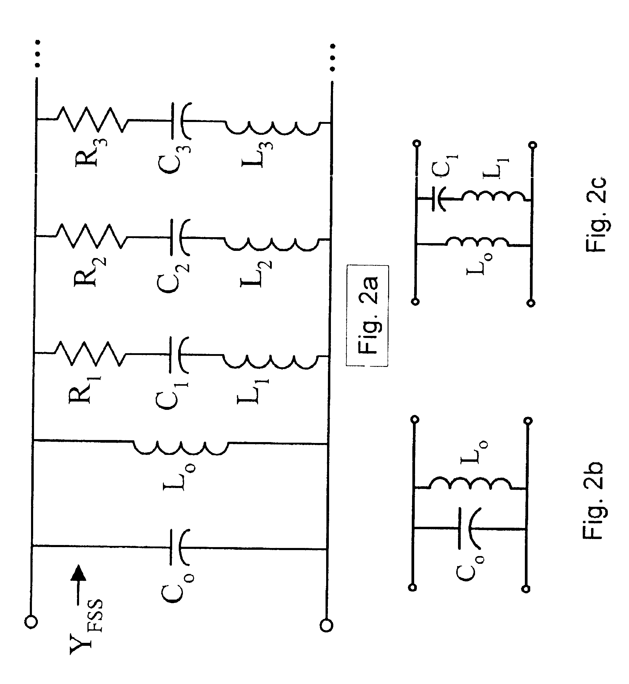
[0075]The frequency selective surfaces (FSS) in the embodiments below are electrically-thin, periodic, printed circuit boards. A FSS may be formed from a multi-layer printed circuit board, not just a single thin layer of metal, or just a single layer of metal etched on a dielectric layer. In currently pending patent application Ser. No. 09 / 678,128 filed Oct. 4, 2000 and entitled “Multi-resonant High-Impedance Electromagnetic Surfaces,” herein incorporated by reference, Diaz and McKinzie teach that electrically thin FSS structures can be accurately modeled, in general, with effective sheet admittance Y(ω) using the second Foster canonical form as an equivalent circuit: Y⁡(ω)=jω⁢ ⁢C0+1jω⁢ ⁢L0+∑ n=1⁢ N⁢ ⁢1Rn+jω⁢ ⁢Ln+1jω⁢ ⁢Cn

[0076]This admittance function, Y(ω), is related to the FSS sheet capacitance (C=∈1t∈0t) by the relation Y=jωC. The corresponding equivalent circuit is shown in FIG. 2a. Each series RLC branch manifests an intrinsic higher order resonance of the FSS. For an FSS made...


PUM


Abstract

DC inductive FSS technology is a printed slow wave structure usable for reduced size resonators in antenna and filter applications of wireless applications. It is a dispersive surface defined in terms of its parallel LC equivalent circuit that enhances the inductance and capacitance of the equivalent circuit to obtain a pole frequency as low as 300 MHz. The effective sheet impedance model has a resonant pole whose free-space wavelength can be greater than 10 times the FSS period. A conductor-backed DCL FSS can create a DC inductive artificial magnetic conductor (DCL AMC), high-impedance surface with resonant frequencies as low as 2 GHz. Lorentz poles introduced into the DCL FSS create multi-resonant DCL AMCs. Antennas fabricated from DCL FSS materials include single-band elements such as a bent-wire monopole on the DCL AMC and multi-band (dual and triple) shorted patches, similar to PIFAs with the patch/lid being a DCL FSS.

Description

BACKGROUND[0001]This application is a non-provisional application claiming priority to provisional application Ser. No. 60 / 310,655, filed Aug. 6, 2001.[0002]The demand for reduced size consumer electronics has produced a corresponding demand for reduced size electronic components used in these electronics. In portable electronics such as cellular telephones, one of the necessary components is an antenna. The most common type of antenna in cellular telephones are whip antennas because they are relatively cheap and simple to fabricate. However, the gain-bandwidth product of a whip antenna is relatively poor and the size is large.[0003]Uniplanar compact photonic bandgap (UC-PBG) structures have been demonstrated in an attempt to reduce the size of antenna. One example of a UC-PBG structure 100 is shown in FIG. 1. This UC-PBG structure 100 contains a thin sheet of metal with a square lattice of Jerusalem crossed slots 112. The UC-PBG structure 100 may also be described as containing a u...

Claims


Application Information

Patent Timeline
Patent Type & Authority Patents(United States)
IPC IPC(8): H01Q19/00H01Q15/02H01Q5/00H01Q5/357H01Q9/04H01Q15/00
CPCH01Q9/0421H01Q5/357H01Q15/0013
Inventor MCKINZIE, III, WILLIAM E.MENDOLIA, GREGORY S.DIAZ, RODOLFO E.
Owner OAE TECH INC
Why Eureka
Try Eureka