Microphone preamplifier

Inactive Publication Date: 2006-07-04
TAYLOR HOHENDAHL ENG
View PDF9 Cites 5 Cited by
  • Summary
  • Abstract
  • Description
  • Claims
  • Application Information

AI Technical Summary

Benefits of technology

[0004]In accordance with one aspect of the present invention, a preamplifier is described where immunity from radio frequency pickup at the output, low power, low input equivalent voltage and current noise, low output impedance, high input impedan

Problems solved by technology

Preamplifier performance in one area is often compromised to achieve performance in another area.
For example, needs for immunity to input noise, large output signals capable of driving large capacitive loads, insens

Method used


Image

  • Microphone preamplifier
  • Microphone preamplifier
  • Microphone preamplifier

Examples


Embodiment Construction

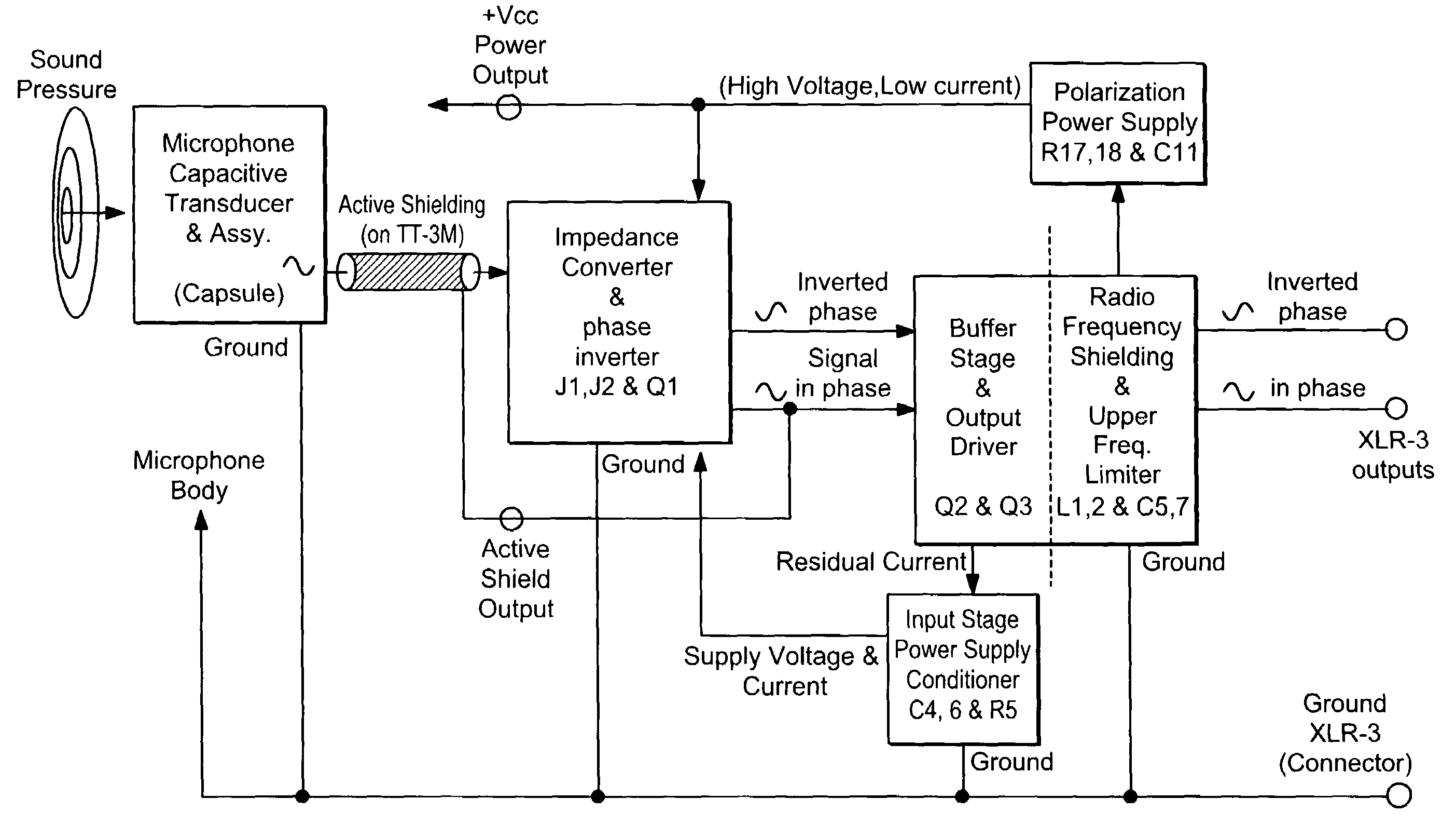
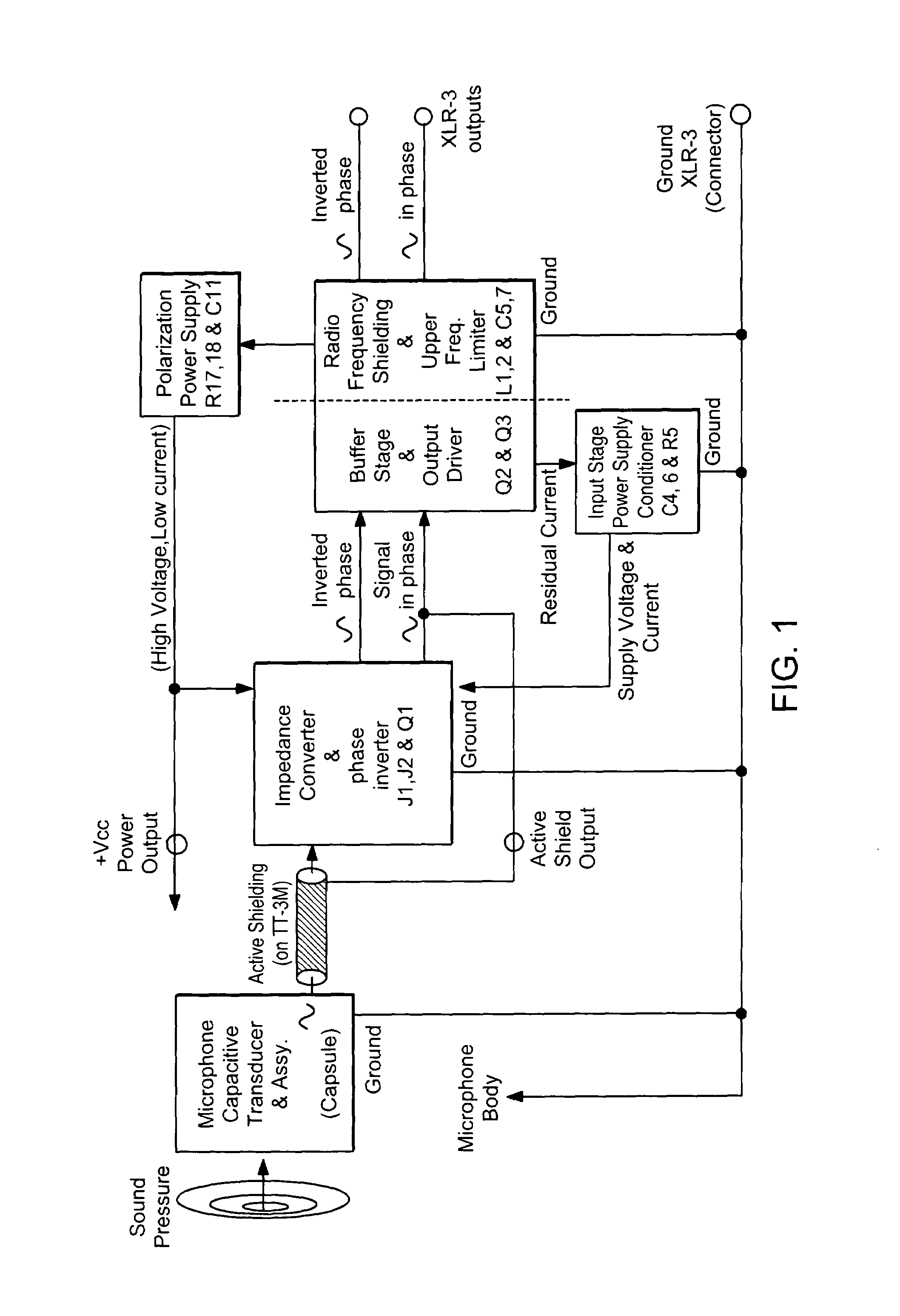
[0012]A functional diagram of an embodiment of the invention is shown in FIG. 1. A capsule, i.e., a microphone capacitive transducer, converts sound pressure into an electrical signal that is communicated to an impedance converter / phase inverter via an actively shielded cable. The in-phase and inverted-phase versions of the signal generated by the impedance converter / phase inverter are each transmitted to a cascade of a buffer stage / output driver and a radio frequency shielder / upper frequency limiter that provides in-phase and inverted-phase output signals.

[0013]Several additional functions address efficiency of design and stability of operation. The radio frequency shielder / upper frequency limiter communicates with a polarization power supply that generates a voltage for the capsule. The buffer stage / output driver communicates with an input stage power supply conditioner that generates supply voltage and current for the impedance converter / phase inverter. The in-phase output of the...


PUM


Abstract

A microphone preamplifier. An electrical signal from a microphone is received via a shielded cable by an input stage cascaded with an output stage. The input stage contains an impedance converter and a phase inverter and receives feedback that reduces input capacitance, actively shields the coaxial cable, and stabilizes the input stage. The output stage contains a buffer and output driver and provides amplified versions of the input stage output. The preamplifier contains means for transformerless phantom powering the microphone and the microphone preamplifier, for sharing current between the input and the output stages, and for limiting the frequency at the output of the microphone.

Description

CROSS REFERENCE TO RELATED APPLICATIONS[0001]This application claims priority from U.S. Provisional Application No. 60 / 324,332, filed Sep. 24, 2001 which is incorporated herein by referenceTECHNICAL FIELD[0002]The present invention relates to a microphone preamplifier, and, more particularly, to a capacitive microphone impedance converter in combination with a class A preamplifier with transformerless balanced low impedance output for phantom powering.BACKGROUND ART[0003]High performance microphones require immediate preamplification of the signal generated by the microphone capsule. Preamplifier performance in one area is often compromised to achieve performance in another area. For example, needs for immunity to input noise, large output signals capable of driving large capacitive loads, insensitivity to variations in supply voltages, low power requirements, and economic design can conflict. As a result, preamplifier designs often satisfy one requirement at the expense of not sati...

Claims


Application Information

Patent Timeline
IPC IPC(8): H03F21/00H03F99/00H03F1/22H03F3/343H03F13/00
CPCH03F1/22H03F13/00H03F3/343
Inventor HOHENDAHL, ANDRES
Owner TAYLOR HOHENDAHL ENG
Why Eureka
Try Eureka