Hybrid gas turbine engine starter-generator

a gas turbine engine and starter technology, applied in the direction of engine starters, electric generator control, dynamo-electric converter control, etc., can solve the problems of relative complex and heavy-duty electronics circuits, voltage and frequency control, and suffer certain drawbacks, so as to reduce the need for cleaning and maintenance, reduce the weight and cost, and increase the wear life of dc brushes

Inactive Publication Date: 2006-07-18
HONEYWELL INT INC
View PDF33 Cites 27 Cited by
  • Summary
  • Abstract
  • Description
  • Claims
  • Application Information

AI Technical Summary

Benefits of technology

[0009]The present invention provides a starter-generator that does not incorporate relatively complex power conversion and frequency control circuits, which reduces the weight and cost as compared to some current starter-generators, that may increase the wear life of the DC brushes, which reduces the need for cleaning and maintenance, and that does not rely on a specially wound stator.

Problems solved by technology

The above-described starter-generator may include relatively complex and heavy power electronics circuits in the control device.
For example, some control devices may include inverters, for converting DC to AC power, rectifiers, for converting AC power to DC power, and potentially complex voltage and frequency control circuits.
Although brush-type DC machines may alleviate the need for some of these complex and heavy electronic circuits, these also suffer certain drawbacks.
For example, the brushes tend to wear fairly quickly, reducing machine reliability, and increasing the need for periodic maintenance and cleaning.
Although this prior approach addresses the noted drawbacks, it too presents certain drawbacks.
In particular, the specially wound main stator, which includes additional segments and windings, is more complex than a conventionally wound stator, which can increase overall costs, and adversely affects power quality when operating in the generator mode.

Method used


Image

  • Hybrid gas turbine engine starter-generator
  • Hybrid gas turbine engine starter-generator
  • Hybrid gas turbine engine starter-generator

Examples


Embodiment Construction

[0026]The following detailed description of the invention is merely exemplary in nature and is not intended to limit the invention or the application and uses of the invention. Furthermore, there is no intention to be bound by any theory presented in the preceding background of the invention or the following detailed description of the invention.

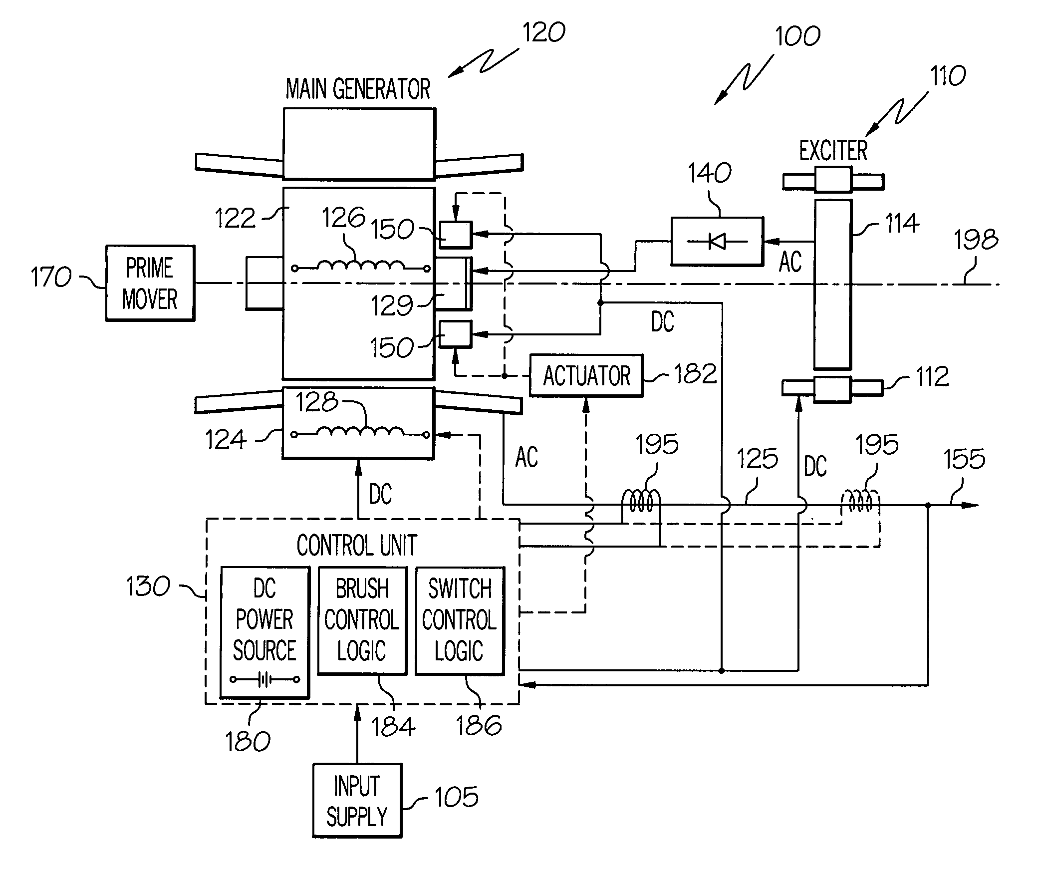
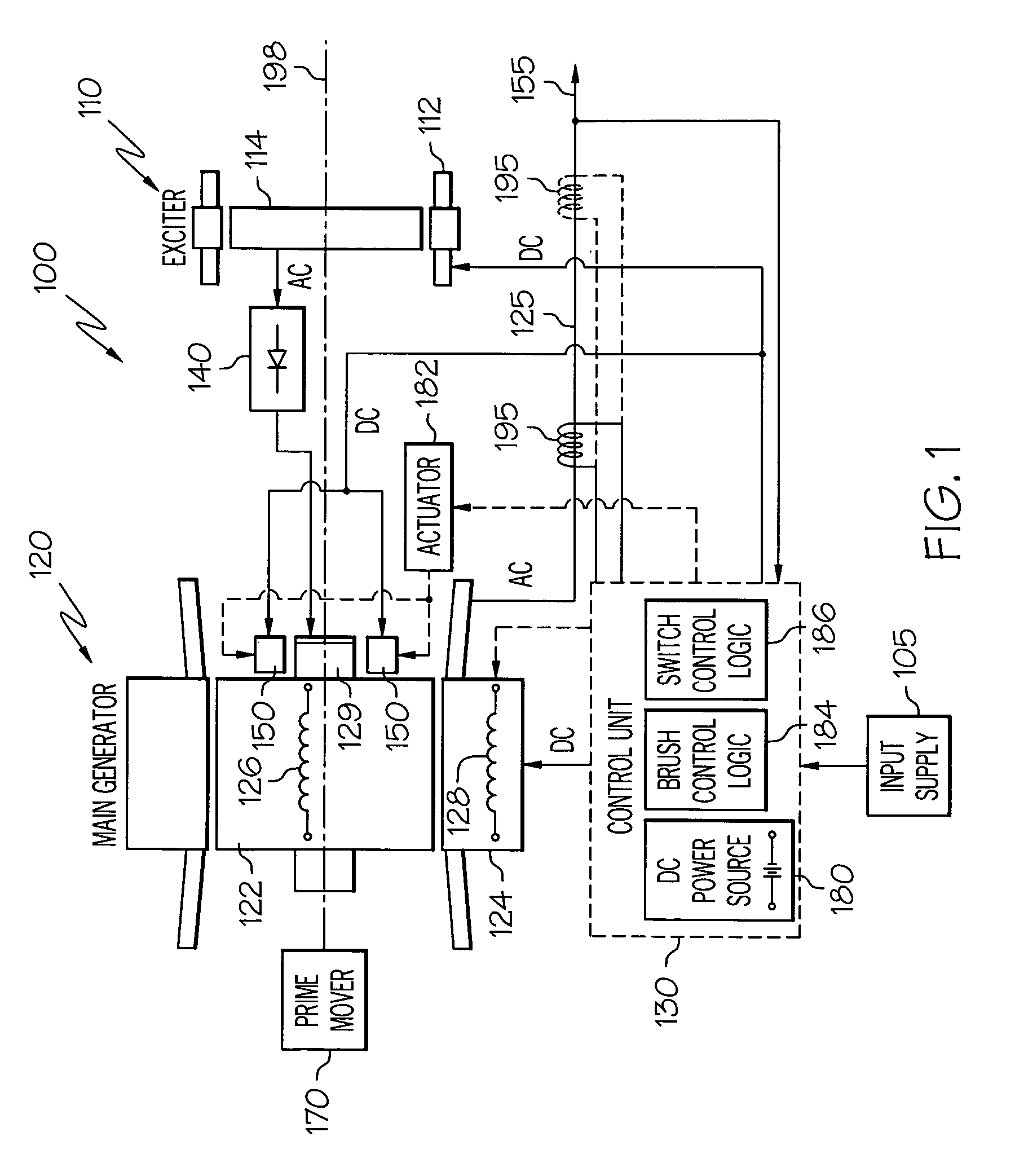
[0027]A functional schematic block diagram of one embodiment of a high speed motor / generator system 100 is shown in FIG. 1. This exemplary motor / generator system 100 includes an exciter 110, a main motor / generator 120, a motor / generator control unit 130, one or more rectifier assemblies 140, and one or more pairs of brushes 150. It is noted that the motor / generator system 100 may be used as a starter-generator, operable at various speeds, for a gas turbine engine in aircraft, space, marine, land, or other vehicle-related applications where gas turbine engines are used. For aircraft applications, gas turbine engines are used for propulsion (e...


PUM


Abstract

A rotating electrical machine, such as an aircraft starter-generator, that may be operated in either a DC motor mode or an AC generator mode. The machine includes a conventionally wound main stator that is selectively configurable as a multi-pole AC stator and a multi-pole DC stator. The machine also includes rotor windings that are configured to be selectively coupled to either an exciter or a plurality of commutator segments, and DC brushes that are selectively moveable into, and out of, electrical contact with the commutator segments, to thereby electrically couple and decouple a DC power source to and from, respectively, the rotor windings.

Description

TECHNICAL FIELD[0001]The present invention relates to rotating electrical machines such as starter-generators for gas turbine engines and, more particularly, to a hybrid starter-generator that is selectively convertible between operation as an AC generator and a DC motor.BACKGROUND[0002]An aircraft may include various types of rotating electrical machines such as, for example, generators, motors, and motor / generators. Motor / generators are used as starter-generators in some aircraft, since this type of rotating electrical machine may be operated in both a motor mode and a generator mode. A starter-generator may be used to start the engines or auxiliary power unit (APU) of an aircraft when operating as a motor, and to supply electrical power to the aircraft power distribution system when operating as a generator. Thus, when operating as a motor, a starter-generator may be designed to supply mechanical output torque sufficient to start the engines.[0003]One particular type of aircraft ...

Claims


Application Information

Patent Timeline
Patent Type & Authority Patents(United States)
IPC IPC(8): H02P9/44
CPCH02K19/16H02P9/302H02P25/12H02K23/52H02K19/36H02K19/38H02P2101/30
Inventor XU, MINGZHOUDUDDECK, MICHAEL W.PEARSON, WAYNE T.SCHERZINGER, WILLIAM M.STOUT, DAVID E.
Owner HONEYWELL INT INC
Why Eureka
Try Eureka