

Common-mode filter
a filter and common-mode technology, applied in the field of common-mode filters, can solve the problems of reducing the cutoff frequency, reducing the insulation resistance of interline voltage, so as to achieve high reliability and high withstand voltag
- Summary
- Abstract
- Description
- Claims
- Application Information
AI Technical Summary
Benefits of technology
Problems solved by technology
Method used
Image

Examples
first embodiment
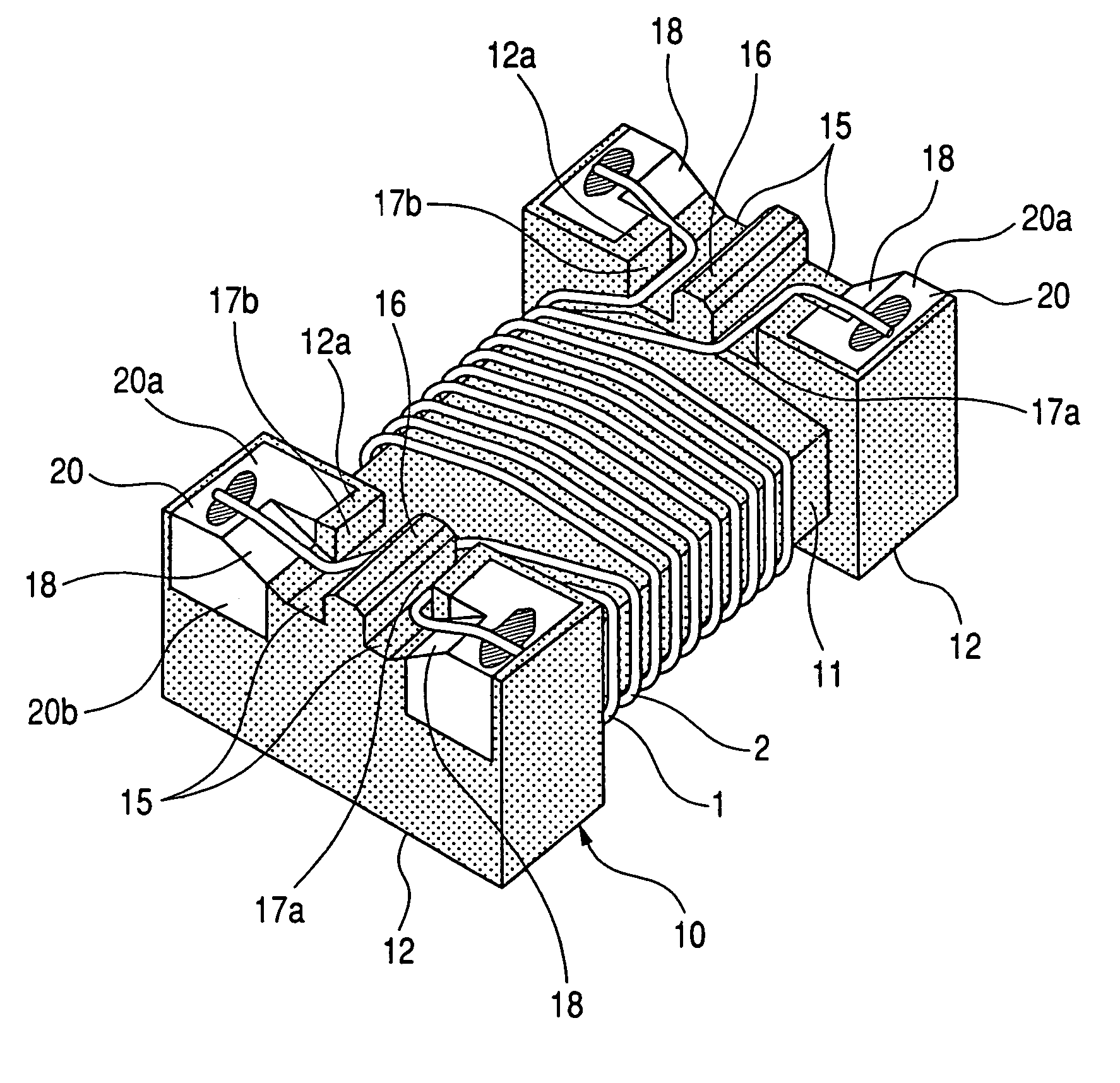
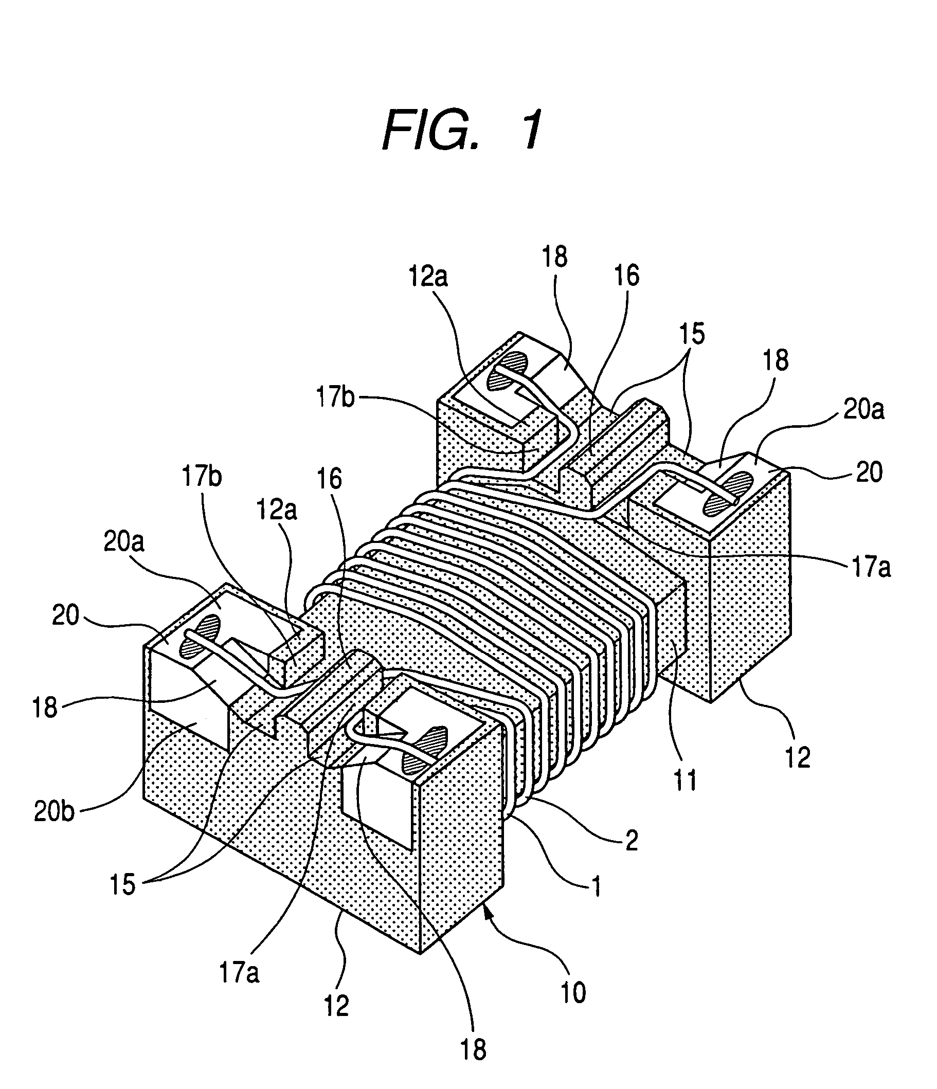
[0020]FIGS. 1 and 2 show a common-mode filter according to the invention. FIG. 1 is a perspective view of the common-mode filter in the case where the bottom side (mount surface side) of the common-mode filter faces upward. FIG. 2 is a bottom view enlargedly showing a wire end joint portion of the common-mode filter. In FIGS. 1 and 2, the reference numeral 10 designates a magnetic drum type core made of a magnetic substance. The magnetic drum type core 10 includes a core portion 11, and a pair of quadrangular flange portions 12 disposed on opposite sides of the core portion 11. Each of the quadrangular flange portions 12 in the drum type core 10 has two electrodes 20 formed by metal paste baking, metal plating or the like. Each of the electrodes 20 has a lower electrode portion (user electrode portion) 20a located in a lower surface (mount surface) of each of opposite end portions of the quadrangular flange portion 12, and a side electrode portion 20b located in a side surface (oute...
second embodiment
[0060]FIG. 4 shows a vertical section taken along the central positions of the quadrangular flange portions 12 of the drum type core 10 in the common-mode filter according to the invention. In this embodiment, concave grooves 31 and 32 are formed in the core portion 11 of the drum type core 10 so that the concave grooves 31 and 32 are used as concave portions for positioning the pair of wires 1 and 2 respectively. The wire 1 is wound on the core portion 11 while positioned by the concave groove 31. The wire 2 is wound on the core portion 11 while positioned by the concave groove 32. In this case, the inter-wire distance (a) between the wires 1 and 2 and the winding pitch (b) between adjacent turns in each of the wires 1 and 2 are decided by the positions of the concave grooves 31 and 32 in advance.
[0061]In accordance with the second embodiment, variation in inter-wire distance (a) between the wires 1 and 2 and variation in winding pitch (b) between adjacent turns in each of the wire...
fourth embodiment
[0064]FIG. 6 shows the invention. In this embodiment, the pair of wires 1 and 2 are wound on the core portion 11 of the drum type core 10, further led out through the two lead-out groove portions 17a and 17b (into which each groove 15 is separated by corresponding one of the separation protrusions 16) and connected to the side electrode portions 20b of the electrodes 20 by thermal contact bonding, soldering or the like (while separated by the separation protrusions 16).
[0065]According to the fourth embodiment, the thickness of each of the lower electrode portions 20a on the actually mounting side is not increased because ends of the wires are connected to the side electrode portions 20b. Accordingly, variation in height can be reduced to attain a low height. Incidentally, because other configuration, operation and effect of the fourth embodiment are the same as those of the third embodiment, parts the same as or equivalent to those in the third embodiment are denoted by the same ref...
PUM
 Abstract
Description
Claims
Application Information