Shift register and driving method thereof
a technology of shift register and driving method, which is applied in the direction of digital storage, multiple input and output pulse circuits, instruments, etc., can solve the problems of increasing layout area and power consumption, increasing power consumption, and difficulty in high frequency operation, and achieves low power consumption
- Summary
- Abstract
- Description
- Claims
- Application Information
AI Technical Summary
Benefits of technology
Problems solved by technology
Method used
Image
Examples
embodiment mode 1
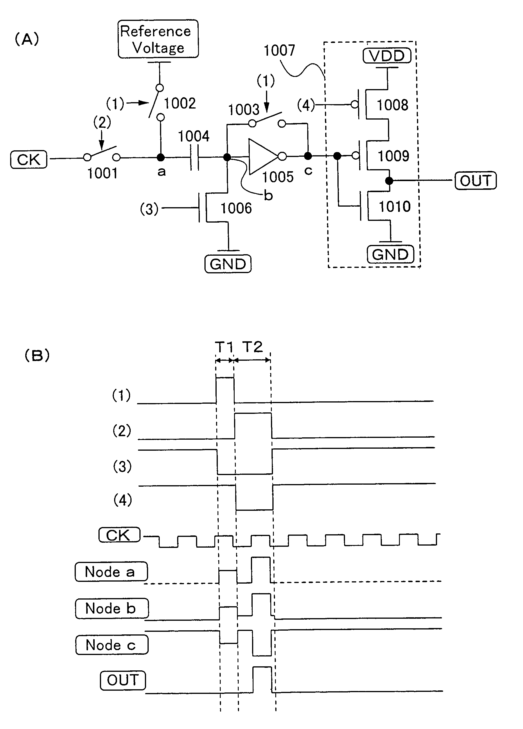
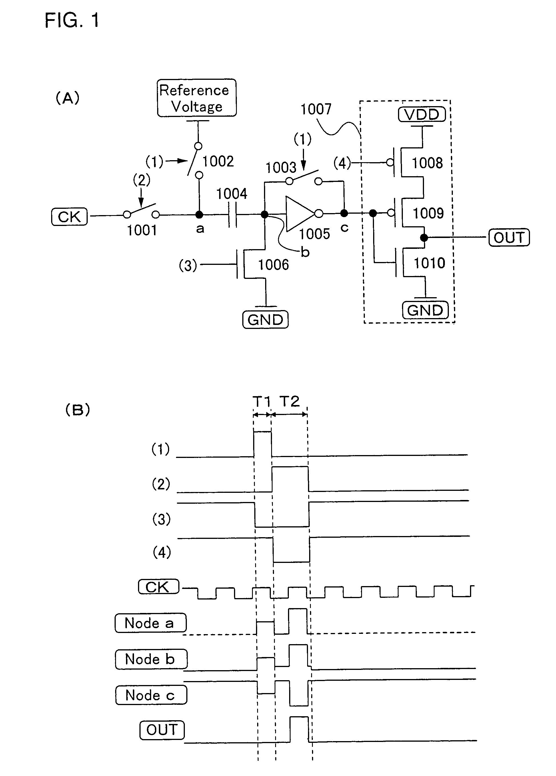
[0084]FIG. 1A shows a first structure of a level shifter which amplifies a CK signal of the shift register of the invention.
[0085]The level shifter of Embodiment Mode 1 includes a switch 1001 for receiving a CK signal, a reference switch 1002, a switch 1003 for setting a threshold value, a capacitor means 1004, a correction inverter 1005, a switch 1006 for fixing a potential, and an output inverter 1007. The output inverter 1007 includes a first P-type TFT 1008, a second P-type TFT 1009, and an N-type TFT 1010.
[0086]The switch 1001 for receiving a CK signal is controlled to be turned ON / OFF by a signal (2) generated from an output pulse of the shift register to supply a CK signal. The reference switch 1002 is controlled to be turned ON / OFF by a signal (1) generated from an output pulse of the shift register to supply a reference voltage to a connection of the switch for receiving CK 1001 and the capacitor means 1004. The input portion and the output portion of the correction inverte...
embodiment mode 2
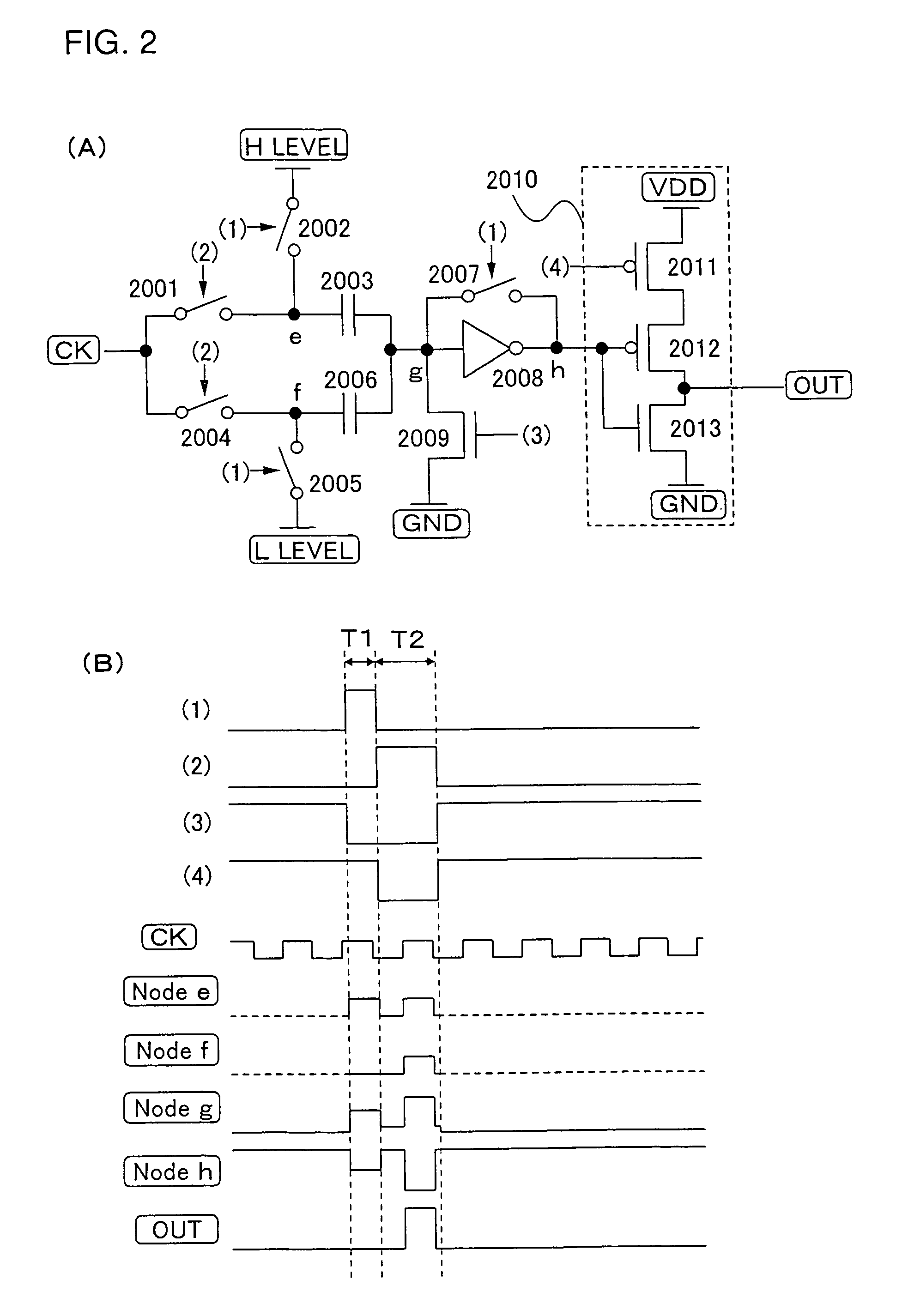
[0100]FIG. 2A shows a second structure of a level shifter which amplifies a CK signal of the shift register of the invention.
[0101]Described in Embodiment Mode 1 is the case of using the intermediate potential of a CK signal as the reference potential. In Embodiment Mode 2, a CK signal is amplified by using H-level and L-level of the CK signal as the reference potential instead Of the intermediate potential.
[0102]The level shifter in this embodiment mode includes a first switch 2001 for receiving a CK signal and a second switch 2004 for receiving a CK signal, a first reference switch 2002 and a second reference switch 2005, a capacitor means 2003 for setting H-level and a capacitor means 2006 for setting L-level, a switch 2007 for setting a threshold value, a correction inverter 2008, a switch 2009 for fixing a potential, and an output inverter 2010. The output inverter 2010 includes a first P-type TFT 2011, a second P-type TFT 2012, and an N-type TFT 2013.
[0103]A capacitor means co...
embodiment mode 3
[0110]FIG. 3 shows a third structure of a level shifter which amplifies a CK signal of a shift register of the invention.
[0111]In Embodiment Modes 1 and 2, a potential of an input portion of a correction inverter changes from a threshold potential by approximately half of a CK signal amplitude when a CK signal is received. Described in Embodiment Mode 3 is the case of changing the potential by the equivalent to a CK signal amplitude.
[0112]The level shifter of this embodiment mode has a first switch 3001 for receiving a CK signal and a second switch 3008 for receiving a CK signal, a first reference switch 3002 and a second reference switch 3009, a first capacitor means 3003, a second capacitor means 3007, a third capacitor means 3010, a fourth capacitor means 3014 and a fifth capacitor means 3015, a first correction inverter 3005 and a second correction inverter 3012, a first switch 3004 for setting a threshold value and a second switch 3011 for setting a threshold value, a first swi...
PUM
 Abstract
Description
Claims
Application Information
 - R&D
- Intellectual Property
- Life Sciences
- Materials
- Tech Scout
- Unparalleled Data Quality
- Higher Quality Content
- 60% Fewer Hallucinations
Browse by: Latest US Patents, China's latest patents, Technical Efficacy Thesaurus, Application Domain, Technology Topic, Popular Technical Reports.
© 2025 PatSnap. All rights reserved.Legal|Privacy policy|Modern Slavery Act Transparency Statement|Sitemap|About US| Contact US: help@patsnap.com


