
Non-blocking, multi-context pipelined processor

a pipelined processor and non-blocking technology, applied in the field of packet switching controllers, can solve the problems of blockage of stages, underutilized processing capabilities of current stages, and typical carrying of execution of conditional branch instructions, so as to improve throughput and processing efficiency

Active Publication Date: 2006-07-18
ALCATEL INTERNETWORKING PE
View PDF3 Cites 43 Cited by
  • Summary
  • Abstract
  • Description
  • Claims
  • Application Information

AI Technical Summary

Benefits of technology

[0007]The present invention is directed to efficiently utilizing the packet processing capabilities of a packet processor by concurrently processing multiple packets within various pipelined stages.
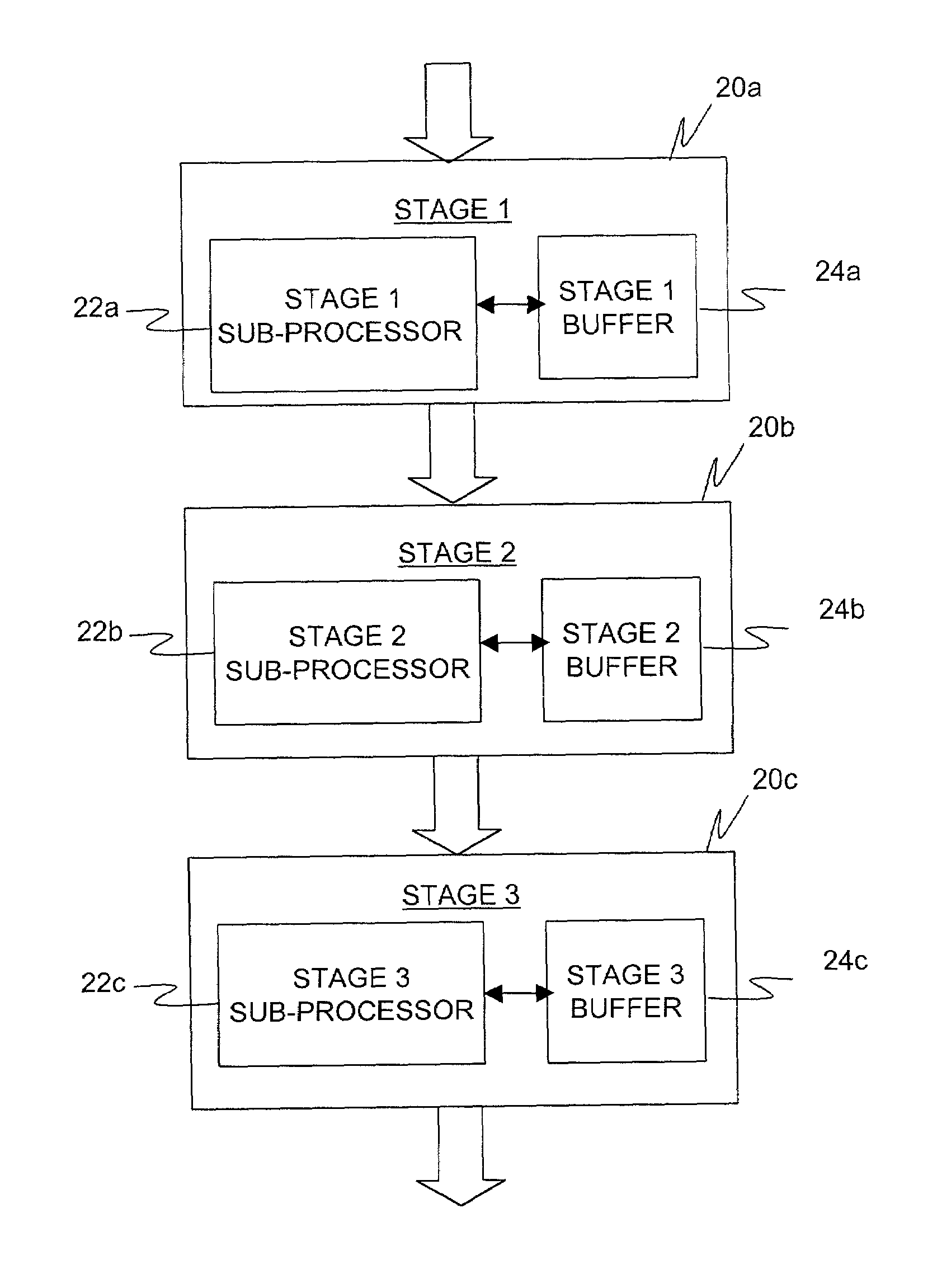
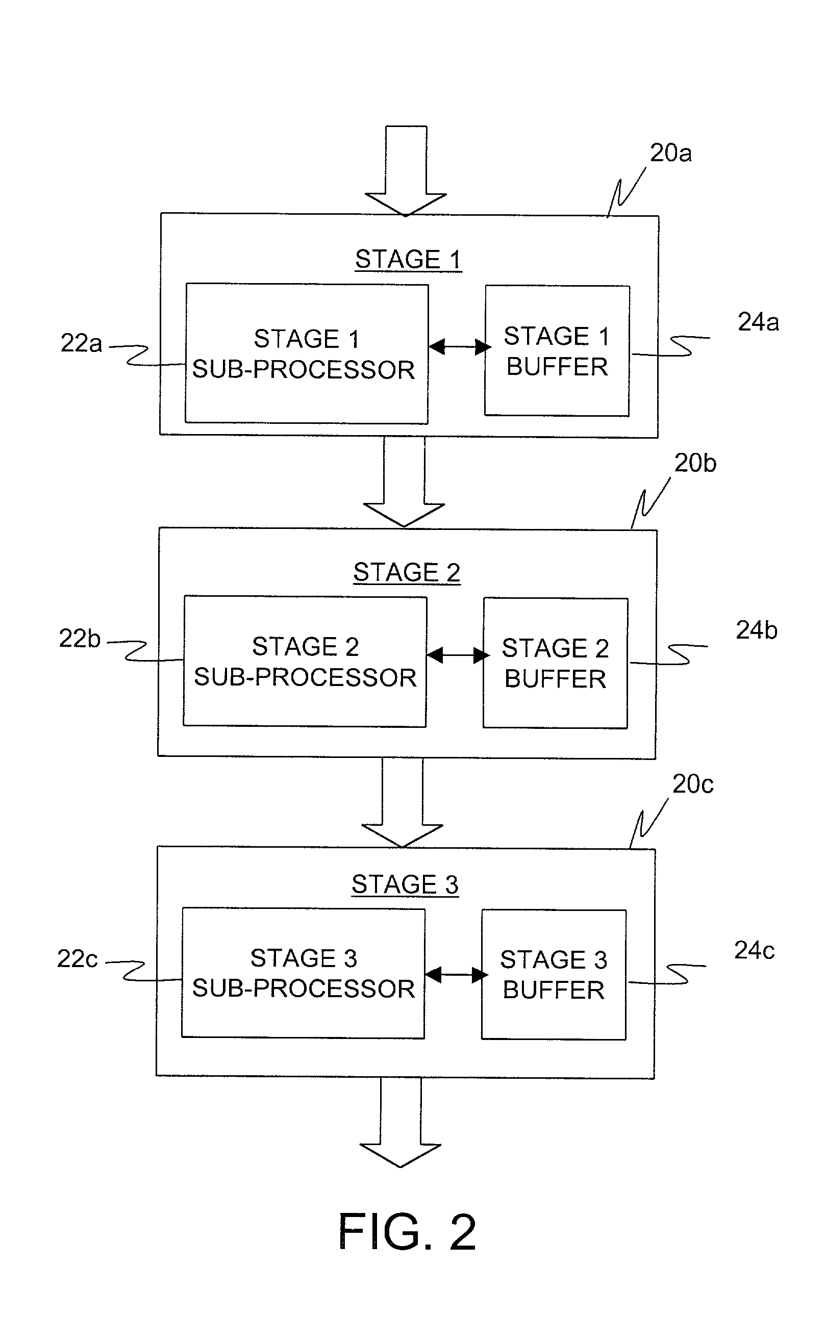
[0012]It should be appreciated, therefore, that the present invention allows efficient utilization of the packet processing capabilities of a packet processor. The switching of packets being processed within a particular stage allows a packet that is done processing early to pass another that is still being processed. Furthermore, the switching of packets to process a next packet if a stall is encountered in the processing the current packet allows the processor to be fully utilized while awaiting processing results and / or without the risk of penalty of branch misprediction.

Problems solved by technology

One problem with the described conventional pipelined packet processors is that the stages are blocking.
Thus, the processing capabilities of the current stage may become underutilized while awaiting for the next stage to complete processing.
Another problem with existing processor technology is the execution of conditional branch instructions typically carried out during packet processing at each stage.
Both of these solutions can result in severe timing penalties.
Waiting for the actual result can substantially slow-down processing, while proceeding based on a predicted result can lead to loading of incorrect instructions that may later have to be flushed.

Method used


Image

  • Non-blocking, multi-context pipelined processor
  • Non-blocking, multi-context pipelined processor
  • Non-blocking, multi-context pipelined processor

Examples


Embodiment Construction

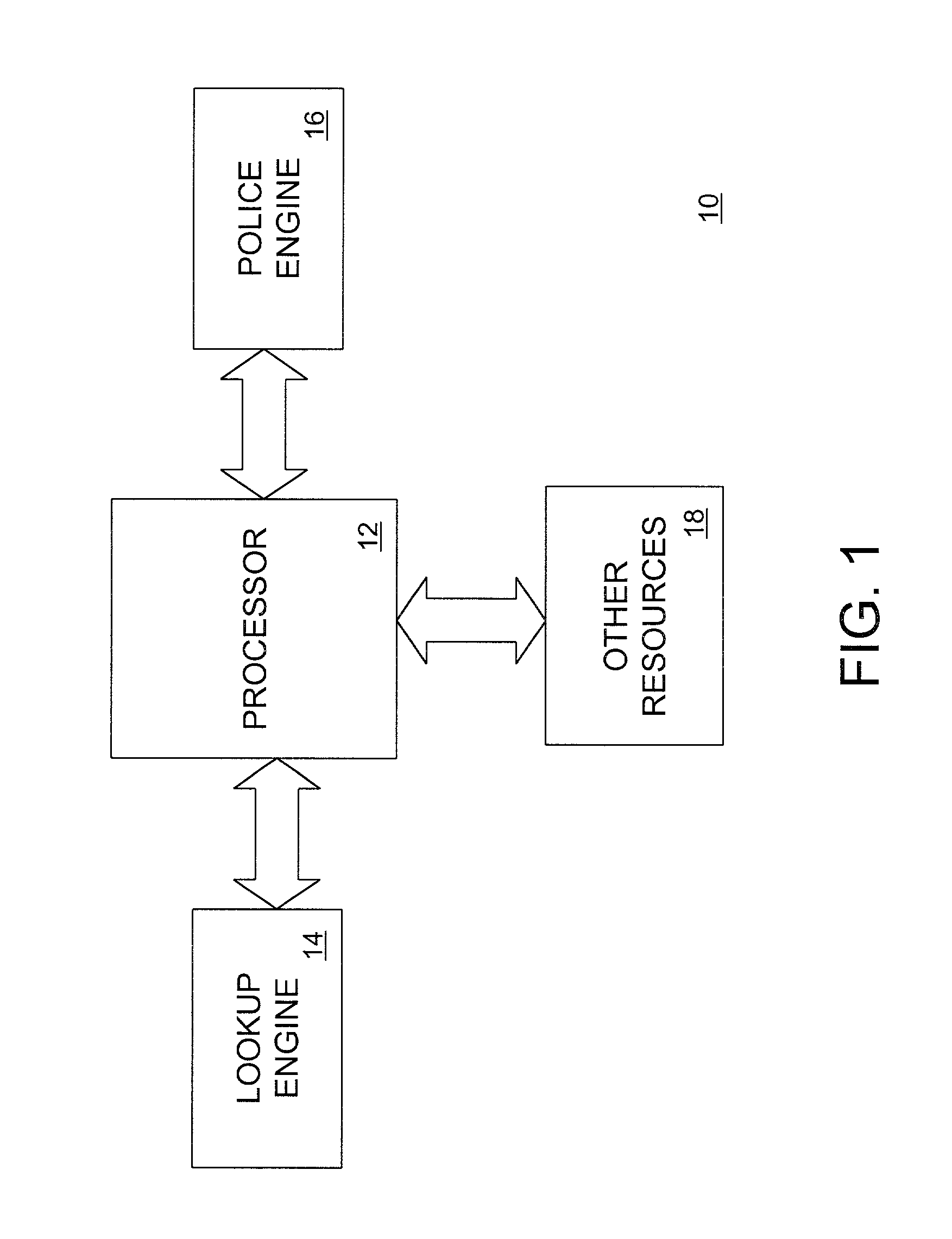
[0021]FIG. 1 is a block diagram of a packet switching controller 10 for classifying and routing incoming flows of packets. The packet switching controller preferably includes a packet processor 12 coupled to various resources according to one embodiment of the invention. The packet processor 12 may be implemented as an application specific integrated circuit (ASIC), but may also be implemented in any known hardware, firmware, or both.

[0022]The packet processor 12 preferably includes multiple sub-processors pipelined in series and operating independently of each other. The independent operation of the sub-processors allows the concurrent processing of different packet data at different stages of the pipeline. In addition, each sub-processor is also internally pipelined to allow current processing of multiple instructions associated with one or more packets within each stage.

[0023]The various resources coupled to the processor 12 include one or more lookup engines 14, police engines 1...


PUM


Abstract

A packet processor whose processing capabilities are optimized by concurrently processing multiple packets within various pipelined stages. At each stage, multiple packets are processed via an internally pipelined sub-processor. In one embodiment, the packets are processed in a round robin fashion. When a particular packet is done processing at a particular stage, it may pass another packet whose processing is not complete, and move to a next stage. In another embodiment, a packet is processed until a conditional branch instruction or any other instruction causing a potential stall is encountered. If such an instruction is encountered, a next available packet is selected and processed instead of wasting processing cycles during the stall, or proceeding with the processing of the current packet based on a predicted result. The sub-processor resumes processing of the packet once the stall is over.

Description

CROSS-REFERENCE TO RELATED APPLICATIONS[0001]This application claims the benefit of U.S. provisional application Nos. 60 / 246,447 entitled “High Speed Network Processor” filed Nov. 7, 2000, and 60 / 278,310 entitled “Non-Blocking, Multi-Context Pipelined Processor” filed Mar. 23, 2001, the contents of which are incorporated herein by reference.FIELD OF THE INVENTION[0002]This invention relates generally to packet switching controllers in a data network, and more particularly, to maximizing usage of a pipelined packet processor in processing incoming data packets.BACKGROUND OF THE INVENTION[0003]Legacy packet processors complete all processing tasks on a first packet data before starting processing a second packet data. Conventional pipelined packet processors have streamlined packet processing relative to legacy packet processors by allowing processing to begin on the second packet data before completing processing on the first packet data. Such conventional pipelining is generally acc...

Claims


Application Information

Patent Timeline
IPC IPC(8): G06F9/38G06F15/78H04L12/56H04L29/06
CPCG06F9/3851G06F9/3867G06F15/8053H04L47/6205H04L49/90H04L29/06H04L69/18H04L9/40
Inventor VAN HOOF, WERNERWHEELER, JERROLDTALLEGAS, MATHIEU
Owner ALCATEL INTERNETWORKING PE
Learn More