Endovascular graft

Inactive Publication Date: 2006-07-25
BOSTON SCI CORP
View PDF680 Cites 139 Cited by
  • Summary
  • Abstract
  • Description
  • Claims
  • Application Information

AI Technical Summary

Benefits of technology

[0008]A proximal neck portion may be secured to the proximal inflatable cuff. The proximal neck portion has a flexible tubular structure that has a diameter similar to the proximal inflatable cuff. The proximal neck portion can be configured as a straight tubular section or can be tapered distally or proximally to an increased or decreased diameter. Preferably, the proximal neck portion is secured and sealed to the proximal inflatable cuff and tapers proximally to an increased diameter so as to engage the inside surface of a vessel wall which provides a sealing function in addition to that of the proximal inflatable cuff. Such a configuration also smoothes the transition for fluid flow from the vessel of a patient to the lumen or channel within the endovascular graft. The proximal neck por

Problems solved by technology

Such conditions require intervention due to the severity of the sequelae, which frequently is death.
However, such a procedure requires a surgical cut down to access the vessel, which in turn can result in a catastrophic rupture of the aneurysm due to the decreased external pressure from the organs and tissues surrounding the aorta, which are moved during the procedure to gain access to the vessel.
Accordingly, surgical procedures have a high mortality rate due to the possibility of the rupture discussed above in addition to other factors.
Other factors can include poor physical condition of the patient due to blood loss, anuria, and low blood pressure associated with the aortic abdominal aneurysm.
One of the primary deficiencies of the existing percutaneous devices and metho

Method used


Image

  • Endovascular graft
  • Endovascular graft
  • Endovascular graft

Examples


Embodiment Construction

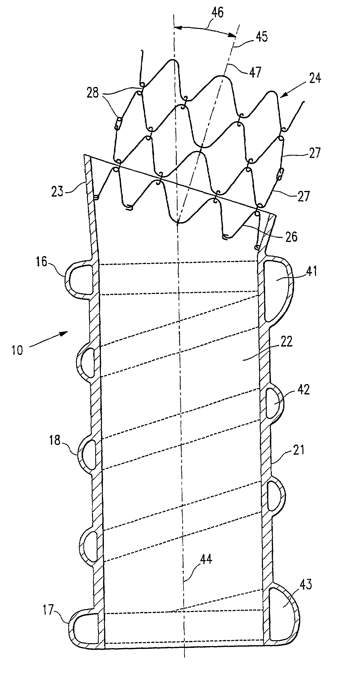
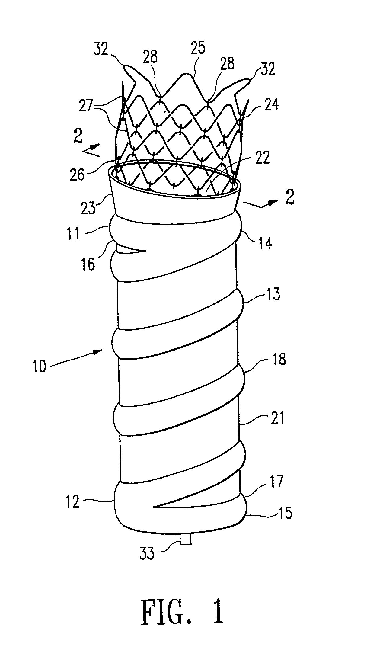
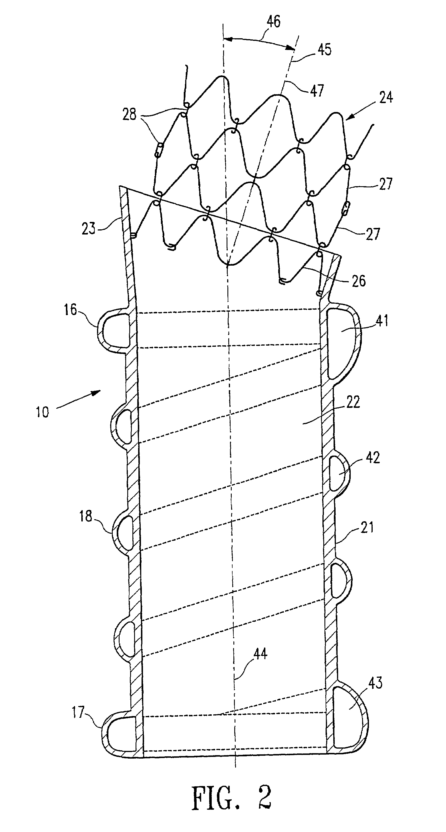
[0036]FIG. 1 shows a perspective view of an endovascular graft 10 having features of the present invention and having a proximal end 11 and a distal end 12. The graft is supported by an inflatable frame 13 which has a proximal end 14 and a distal end 15 and is shown in its deployed state. The inflatable frame structure 13 has a proximal inflatable cuff 16 at the proximal end 14 and an optional distal inflatable cuff 17 at the distal end 15. The inflatable cuffs 16 and 17 can be annular in shape when deployed, although the cuffs can conform to the shape of the vessel within which they are deployed, and can have an outside diameter or cross sectional dimension of about 10 to about 45 mm, preferably about 16 to about 28 mm. There is at least one elongated inflatable channel 18 disposed between the proximal inflatable cuff 16 and the distal inflatable cuff 17. The inflatable frame 13 can be from about 5 to about 30 cm in length, preferably about 10 to about 20 cm in length. Disposed bet...


PUM


Abstract

An endovascular graft which is configured to conform to the morphology of the vessel to be treated and which is made from an inflatable structure having a proximal end with a proximal inflatable cuff and a distal end with a distal inflatable cuff. At least one elongated inflatable channel is disposed between and in fluid communication with fluid tight chambers of the inflatable cuffs which may contain rupture discs therebetween which can be configured to rupture at different pressures. A thin flexible barrier disposed between the inflatable cuffs and the elongated inflatable channel of the frame so as to form a tubular structure defining a longitudinal channel to confine a flow of blood or other fluid therethrough. The graft may also have an expansion member attached to the proximal end of the graft which is preferably made of linked expandable rings of pseudoelastic shape memory alloy which is self expanding and prevents axial displacement of the graft once it is deployed.

Description

RELATED APPLICATIONS[0001]This application is a continuation of application Ser. No.: 09 / 133,978, filed Aug. 14, 1998, now U.S. Pat. No. 6,395,019 which is a continuation-in-part of Provisional Application No. 60 / 074,112, filed Feb. 9, 1998. The subject matter of each of the above patent applications is incorporated by reference in its entirety herein.BACKGROUND OF THE INVENTION[0002]The present invention relates to a system and method for the treatment of disorders of the vasculature. More specifically, a system and method for treatment of abdominal aortic aneurysm and the like, which is a condition manifested by expansion and weakening of the aorta below the diaphragm. Such conditions require intervention due to the severity of the sequelae, which frequently is death. Prior methods of treating aortic aneurysm have consisted of invasive surgical methods with graft placement within the aorta as a reinforcing member of the artery. However, such a procedure requires a surgical cut dow...

Claims


Application Information

Patent Timeline
IPC IPC(8): A61M29/00A61F2/07A61F2/00A61F2/02A61F2/06A61F2/24A61F2/954A61F2/958
CPCA61F2/07A61F2/06A61F2/958A61F2002/065A61F2002/075A61F2250/0003A61F2250/0039A61F2/915A61F2/945A61F2220/0075A61F2/90A61F2250/0071A61F2230/0034
Inventor CHOBOTOV, MICHAEL V.
Owner BOSTON SCI CORP
Why Eureka
Try Eureka