Methods for manipulating moieties in microfluidic systems

a microfluidic system and moiete technology, applied in electrostatic separators, electrolysis, isotope separation, etc., can solve the problems of not having a general method for manipulating molecules in microfluidic devices, unable to achieve sufficient dc field in aqueous solutions, and unable to cause undesired effects, etc., to achieve the effect of expanding and enhancing the capabilities of molecule manipulation, simplifying and standardizing the design

Inactive Publication Date: 2006-07-25
AVIVA BIOSCI
View PDF39 Cites 353 Cited by
  • Summary
  • Abstract
  • Description
  • Claims
  • Application Information

AI Technical Summary

Benefits of technology

[0008]The present invention addresses these and other related needs in the art. It is an objective of the present invention to provide a general method for manipulating a variety of moieties including molecules. It is another objective of the present invention to make full use of a number of force mechanisms effectively for manipulating the moieties. It is still another objective of the present invention to provide for standardized on-chip manipulation procedure, leading to simplification and standardization of the design of microchips and the associated systems. It is yet another objective of the present invention to expand and enhance the capabilities of molecule manipulation with the choice of microparticles with special physical properties. It is yet another objective of the present invention to provide a general, effective procedure for on-chip molecule manipulation that allows for fully integration of biochip-based analytical systems and processes.

Problems solved by technology

However, up to now, there is not a general method for manipulating molecules in microfluidic devices.
All these methods have many limitations.
Generating sufficient DC field in aqueous solutions without causing undesired effects, e.g., surface electrochemistry, gas bubble generation, is very difficult.
Most importantly, the DC electrical field cannot be readily structured to generate manipulation forces in a versatile way.
Optical radiation force can operate on large molecules, e.g., DNA molecules, but there are certain difficulties in generating 3-D, flexible, optical manipulation forces.
Despite the existence of a number of physical forces applicable to molecule manipulation, several key difficulties exist.
Direct manipulation of many types of molecules with these forces requires extremely high field strength because of the relative small dimensions of molecules, and effective manipulation of molecules is almost impossible.
High field strengths tend to induce undesired fluid motion for manipulation forces such as dielectrophoresis or traveling-wave-dielectrophoresis.
Secondly, certain types of physical forces can be generated on molecules, but the 3-D distributions of these physical forces cannot be readily structured for flexible, versatile handling and manipulation of molecules.
Thirdly, there is still no general method for manipulating and handling molecules in microfluidic systems and devices.
This method has certain limitations.
Reducing such permanent magnet size and handling a large number of these small permanent magnets automatically for manipulation of particles in a chip format will be a very difficult, if not impossible, challenge.
Thus, the method cannot be readily miniaturized and automated.
Furthermore, the permanent magnet-based methods are not applicable to many steps in bioanalytical procedures.
Thus, the biochip-system integration based this method will be difficult, if not impossible.
In summary, the currently available manipulation methods suffer from the following deficiencies: (1) it is difficult to directly apply effective, physical manipulation forces to many types of molecules because of the relative small dimensions of molecules; and (2) some physical forces that can be generated on molecules often have limitations in 3-D structuring of the force distribution and (3) it is difficult to use currently available biochip-based methods for developing fully automated, miniaturized and integrated biochip systems.

Method used


Image

  • Methods for manipulating moieties in microfluidic systems
  • Methods for manipulating moieties in microfluidic systems
  • Methods for manipulating moieties in microfluidic systems

Examples


Embodiment Construction

[0072]A. Definitions

[0073]Unless defined otherwise, all technical and scientific terms used herein have the same meaning as is commonly understood by one of ordinary skill in the art to which this invention belongs. All patents, applications, published applications and other publications and sequences from GenBank and other data bases referred to herein are incorporated by reference in their entirety.

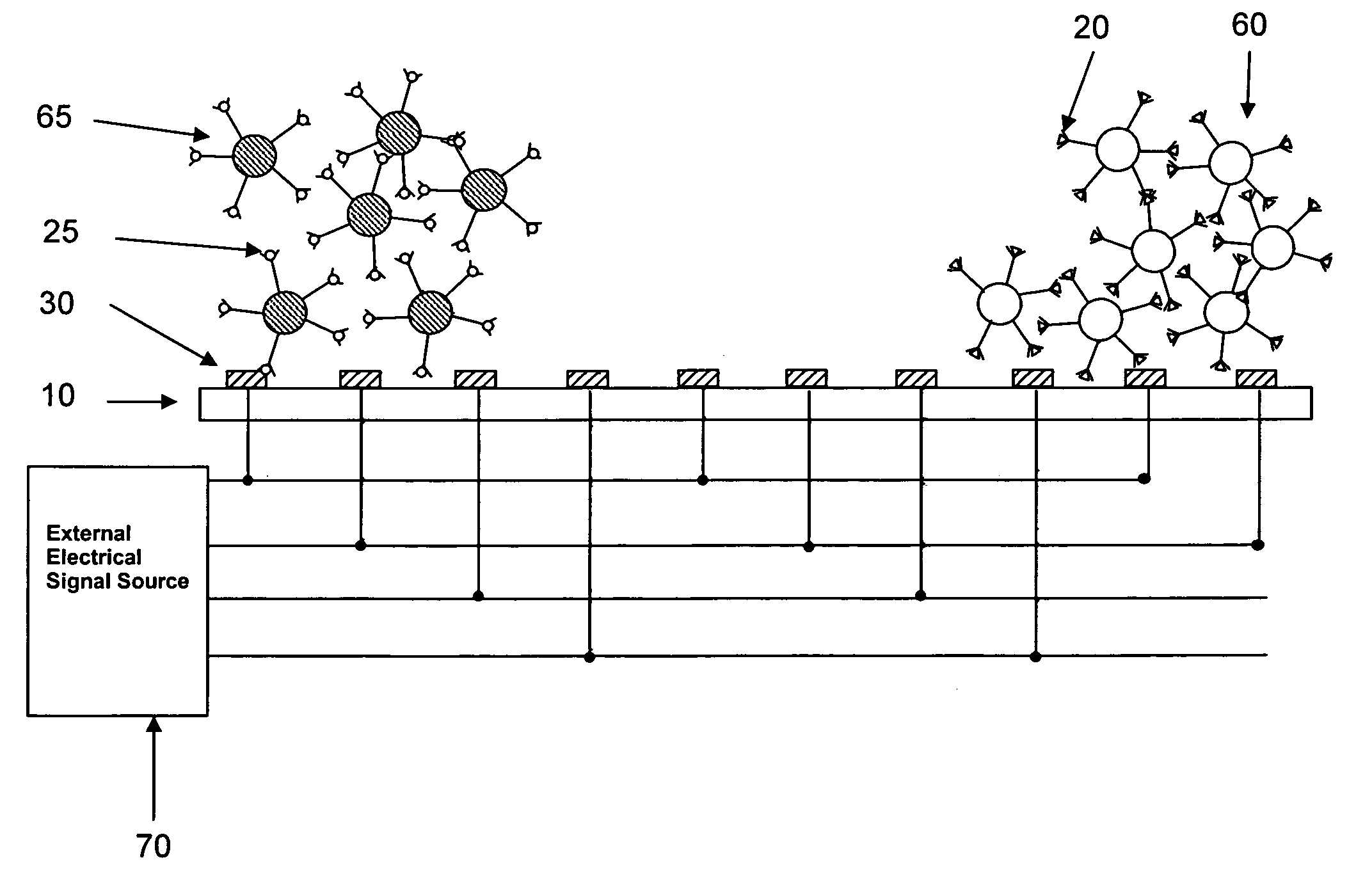
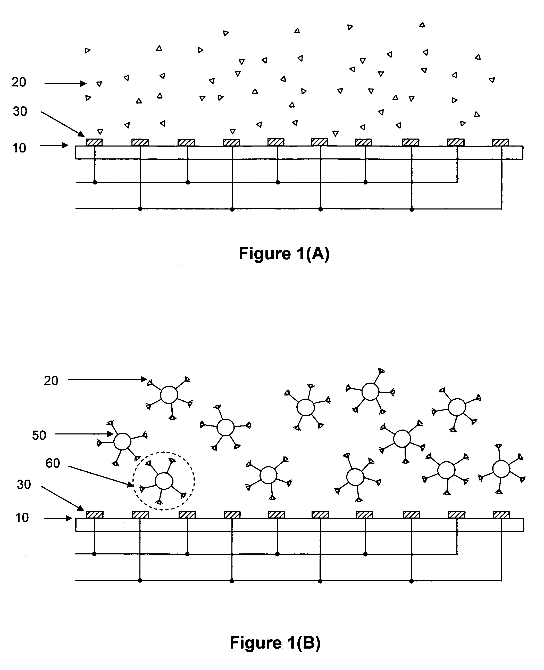
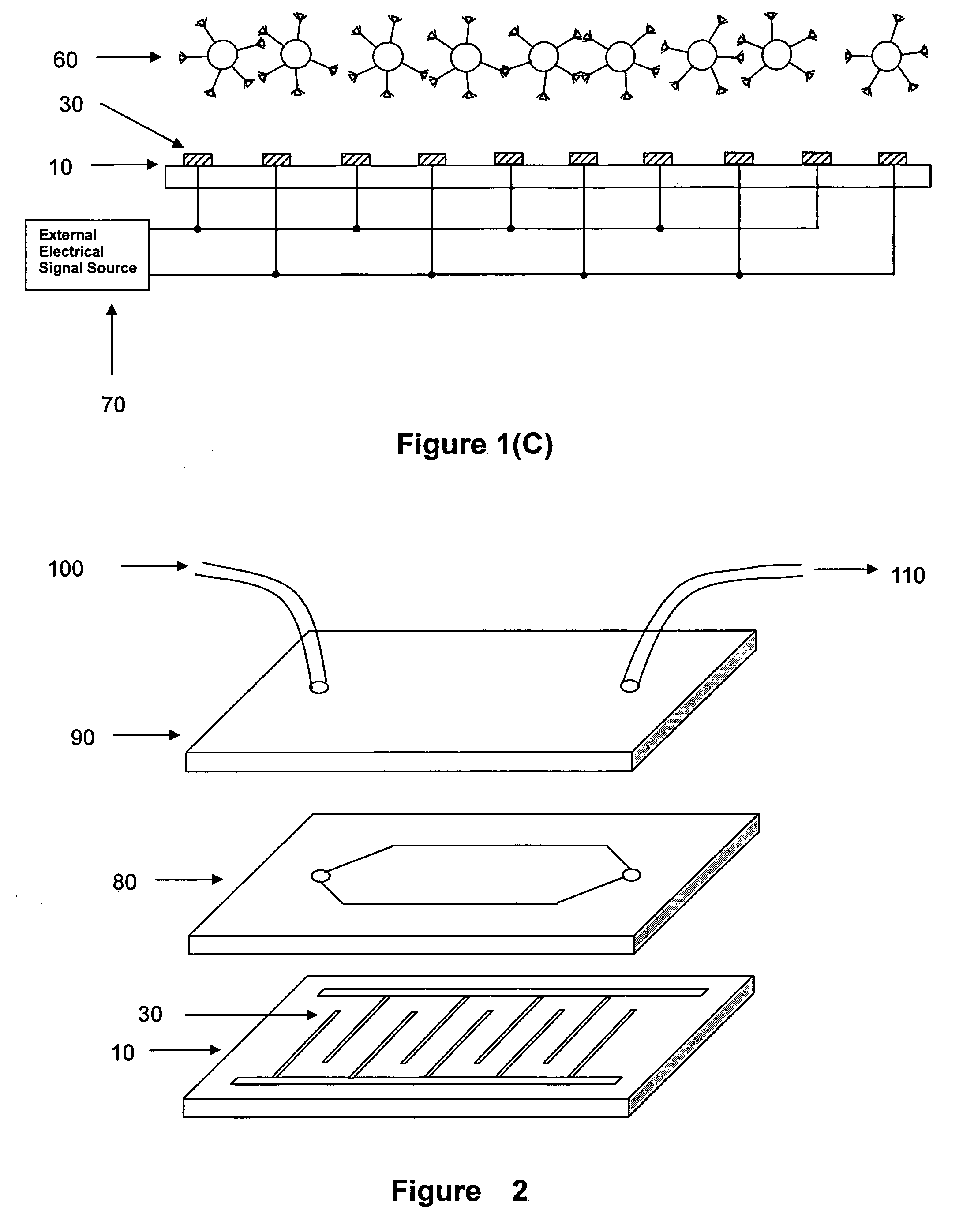
[0074]As used herein, “microfluidic application” refers to the use of microscale devices, e.g., the characteristic dimension of basic structural elements is in the range between less than 1 micron to cm scale, for fluidic manipulation and process, typically for performing specific biological, biochemical or chemical reactions and procedures. The specific areas include, but are not limited to, biochips, i.e., microchips for biologically related reactions and processes, chemchips, i.e., microchips for chemical reactions, or a combination thereof.

[0075]As used herein, “moiety” refers to an...


PUM

PropertyMeasurementUnit
diameteraaaaaaaaaa
sizeaaaaaaaaaa
diameteraaaaaaaaaa

Abstract

This invention relates generally to the field of moiety or molecule manipulation in a chip format. In particular, the invention provides a method for manipulating a moiety in a microfluidic application, which method comprises: a) coupling a moiety to be manipulated onto surface of a binding partner of said moiety to form a moiety-binding partner complex; and b) manipulating said moiety-binding partner complex with a physical force in a chip format, wherein said manipulation is effected through a combination of a structure that is external to said chip and a structure that is built-in in said chip, thereby said moiety is manipulated.

Description

RELATED APPLICATION[0001]This application is related to a Chinese national patent application, 00122631.2 filed Aug. 8, 2000, entitled “METHODS FOR MANIPULATING MOIETIES IN MICROFLUIDIC SYSTEMS.” The disclosure of the above Chinese national patent application is incorporated by reference in its entirety.TECHNICAL FIELD[0002]This invention relates generally to the field of moiety or molecule manipulation in a chip format. In particular, the invention provides a method for manipulating a moiety in a microfluidic application, which method comprises: a) coupling a moiety to be manipulated onto surface of a binding partner of said moiety to form a binding partner-moiety complex; and b) manipulating said binding partner-moiety complex with a physical force in a chip format, wherein said manipulation is effected through a combination of a structure that is external to said chip and a structure that is built-in in said chip, thereby said moiety is manipulated.BACKGROUND ART[0003]Intensive r...

Claims


Application Information

Patent Timeline
Patent Type & Authority Patents(United States)
IPC IPC(8): G01N27/447C12Q1/00G01N33/48B01L3/00B03C5/02C12M1/34C12Q1/04C12Q1/68G01N15/10G01N27/00G01N27/26G01N33/50G01N33/543G01N33/569
CPCB01L3/502761G01N33/569B03C5/028G01N27/745G01N33/54386B01L2200/0668B01L2300/0816B01L2300/0864B01L2400/0415B01L2400/0424B01L2400/043B01L2400/0436B01L2400/0439B01L2400/0454B01L2400/0496B03C2201/26B01L2200/0647
Inventor WANG, XIAOBOWU, LEICHENG, JINGYANG, WEIPINGXU, JUNQUAN
Owner AVIVA BIOSCI
Why Eureka
Try Eureka