System and method for fluorescence monitoring

a fluorescence monitoring and fluorescence technology, applied in the field of fluorescence monitoring systems and methods, can solve the problems of hindering the transfer of thermal energy, the disadvantages of microfuge tubes, and the undesirable use of heat block devices as heat control systems

Inactive Publication Date: 2006-07-25
UNIV OF UTAH RES FOUND
View PDF104 Cites 140 Cited by
  • Summary
  • Abstract
  • Description
  • Claims
  • Application Information

AI Technical Summary

Benefits of technology

[0042]FIG. 6 shows graphically the effect of denaturation time on polymerase chain reaction yields using one thermal cycling device of the present invention.
[0043]FIG. 7 shows graphically the effect of annealing time on polymerase chain reaction specificity and yields using the thermal cycling device of the present invention.

Problems solved by technology

However, the inability to quickly and accurately adjust the temperature of the heat blocks through a large temperature range over a short time period, has rendered the use of heat block type devices undesirable as a heat control system when carrying out processes such as the polymerase chain reaction.
Moreover, the microfuge tubes which are generally used have disadvantages.
The material of the microfuge tubes, their wall thickness, and the geometry of microfuge tubes is a hindrance to rapid heating and cooling of the sample contained therein.
The plastic material and the thickness of the wall of microfuge tubes act as an insulator between the sample contained therein and the surrounding medium thus hindering transfer of thermal energy.
Although water baths have been used in cycling a polymerase chain reaction mixture through a desired temperature versus time profile necessary for the reaction to take place, the high thermal mass of the water (and the low thermal conductivity of plastic microfuge tubes), has been significantly limiting as far as performance of the apparatus and the specificity of the reaction are concerned.
Devices using water baths are limited in their performance.
Also, the water bath apparatus has been found to be very cumbersome due to the size and number of water carrying hoses and external temperature controlling devices for the water.
Further the need for excessive periodic maintenance and inspection of the water fittings for the purpose of detecting leaks in a water bath apparatus is tedious and time consuming.
Finally, it is difficult with the water bath apparatus to control the temperature in the sample tubes with the desired accuracy.
Although the Ray device is somewhat effective in maintaining a constant temperature within an air chamber, it does not address the need for rapidly adjusting the temperature in a cyclical manner according to a temperature versus time profile such as is required for biological procedures such as the polymerase chain reaction.
The devices disclosed in the Howe and Sisti et al. patents are suited for carrying out gas chromatography procedures but do not provide thermal cycling which is substantially any more rapid than that provided by any of the earlier described devices.
Devices such as those described in the Howe and Sisti et al. patents are not suitable for efficiently and rapidly carrying out such reactions.
Despite its usefulness and popularity, the current understanding of PCR is not highly advanced.

Method used


Image

  • System and method for fluorescence monitoring
  • System and method for fluorescence monitoring
  • System and method for fluorescence monitoring

Examples


example 1

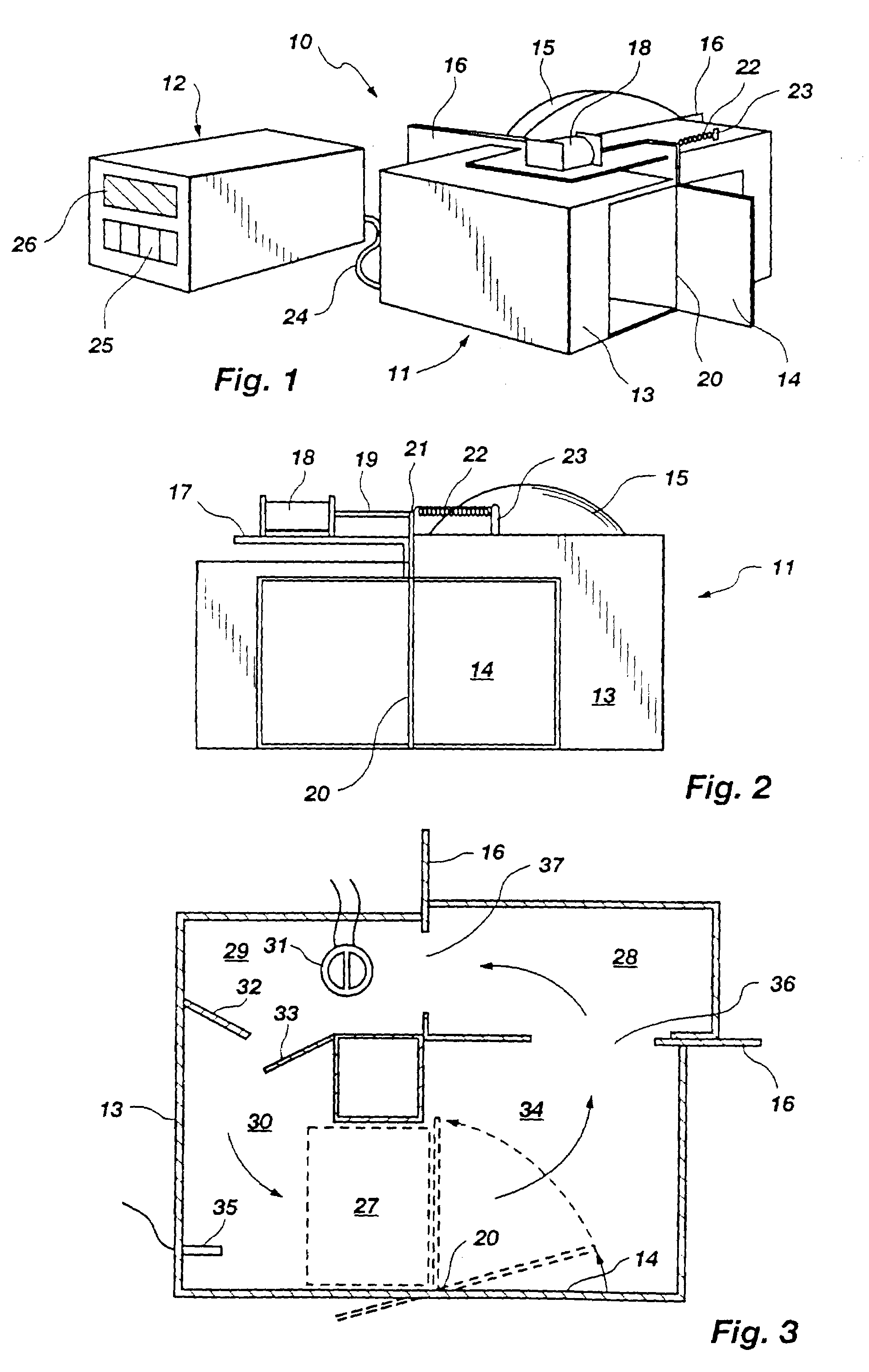
[0111]The polymerase chain reaction was run in a 10 μl volume with 50 ng of human genomic template DNAes, 0.5 mM of each deoxynucleotide, 500 nM of each of two oligonucleotide primers GGTTGGCCAATCTACTCCCAGG (SEQ ID NO:5) and GCTCACTCAGTGTGGCAAAG (SEQ ID NO:6) in a reaction buffer consisting of 50 mM Tris-HCl (pH 8.5 at 25° C.), 3.0 mM magnesium chloride, 20 mM KCl, and 500 μg / ml bovine serum albumin. Thermus aquaticus DNA polymerase (0.4μ) was added, the samples placed in 8 cm long, thin-walled capillary tubes (manufactured by Kimble, Kimax 46485–1), and the ends fused with a laboratory gas burner so that an air bubble was present on both ends of each tube.

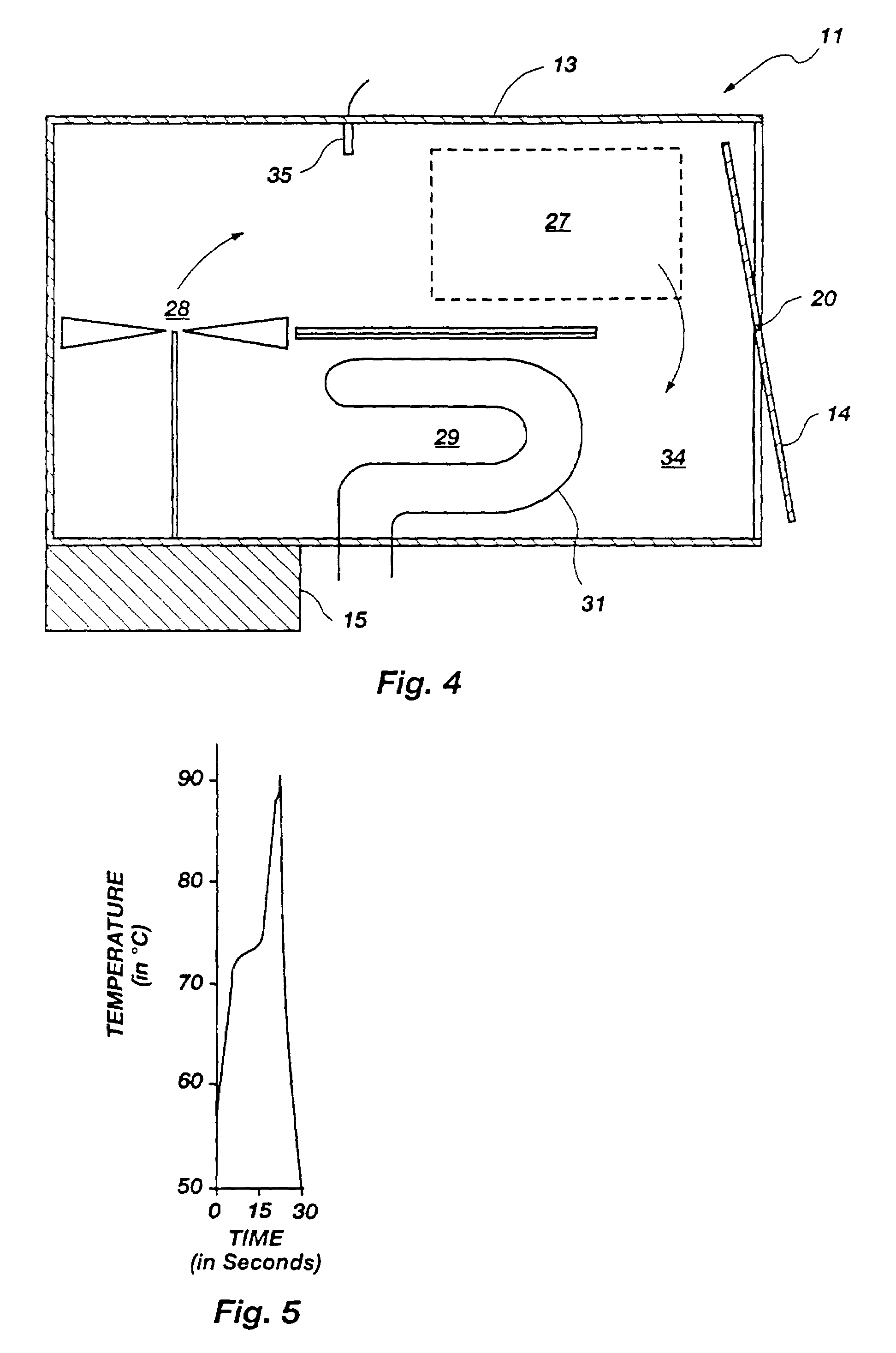
[0112]The capillary tubes were then placed vertically in a holder constructed of 1 mm thick “prepunched perfboard” (manufactured by Radio Shack). The mixture was cycled 30 times through denaturation (90–92° C.), annealing (50–55° C.), and elongation (72–75° C.) to give the temperature versus time profile of FIG. 5. Temperature mon...

example 2

[0144]FIG. 9A shows the results of four different temperature / time profiles (A–D) and their resultant amplification products after thirty cycles (A–D). The profiles A and B in FIG. 9A were obtained using a prior art heating block device using the prior art microfuge tube. As can be seen in FIG. 9A, the transitions between temperatures are slow and many nonspecific bands are present in profiles A and B. Profile B shows improvement in eliminating some of the nonspecific bands (in contrast to profile A) by limiting the time each sample remains at each temperature thus indicating that shorter times produce more desirable results.

[0145]Profiles C and D were obtained using the apparatus of FIGS. 8A–B. As can be seen in FIG. 9A, amplification is specific and, desirably, even though yield is maximal in C (60 second elongation) it is still entirely adequate in D (10 seconds elongation).

[0146]The optimal times and temperatures for the amplification of a 536 bp fragment of β-globin from human ...


PUM

PropertyMeasurementUnit
volumeaaaaaaaaaa
volumeaaaaaaaaaa
diameteraaaaaaaaaa

Abstract

A thermal cycling method and device is disclosed. The device comprises a sample chamber whose temperature can be rapidly and accurately modulated over a range of temperatures needed to carry out a number of biological procedures, such as the DNA polymerase chain reaction. Biological samples are placed in glass micro capillary tubes and then located inside the sample chamber. A programmable controller regulates the temperature of the sample inside the sample chamber. Monitoring of the DNA amplification is monitored by fluorescence once per cycle or many times per cycle. The present invention provides that fluorescence monitoring of PCR is a powerful tool for DNA quantification.

Description

RELATED APPLICATIONS[0001]This application is a continuation-in-part of U.S. patent application Ser. No. 08 / 658,993, filed Jun. 4, 1996, now abandoned, entitled System and Method for Monitoring PCR Processes.[0002]The copending U.S. application filed in the U.S. Patent and Trademark on Jun. 4, 1997 entitled Monitoring Hybridization During PCR as Ser. No. 08 / 869,276 and naming Carl T. Wittwer, Kirk M. Ririe, and Randy P. Rasmussen as inventors is hereby incorporated by reference in its entirety.BACKGROUND[0003]1. The Field of the Invention[0004]This invention relates generally to apparatus which are used to carry out biological processes, such as the polymerase chain reaction. More specifically, the present invention relates to apparatus and methods which carry out thermal cycling and monitoring of various biological reactions, such as the polymerase chain reaction.[0005]2. The Background Art[0006]In numerous areas of industry, technology, and research there is a need to reliably and...

Claims


Application Information

Patent Timeline
Patent Type & Authority Patents(United States)
IPC IPC(8): G01N33/50C12P19/34
CPCB01L3/5025B01L7/52B01L2300/0803B01L2400/0409B01L2300/1844B01L2400/0406B01L2300/0838
Inventor WITTWER, CARL T.RIRIE, KIRK M.RASMUSSEN, RANDY P.HILLYARD, DAVID R.
Owner UNIV OF UTAH RES FOUND
Why Eureka
Try Eureka