
Cooling apparatus for hybrid vehicle

a hybrid vehicle and cooling apparatus technology, applied in the direction of electric propulsion mounting, machines/engines, transportation and packaging, etc., can solve the problems of complicated apparatus structure and impaired loading of vehicles, and achieve the effect of simplifying the apparatus structur

Inactive Publication Date: 2006-08-01
HONDA MOTOR CO LTD
View PDF21 Cites 31 Cited by
  • Summary
  • Abstract
  • Description
  • Claims
  • Application Information

AI Technical Summary

Benefits of technology

The present invention provides a cooling apparatus for a hybrid vehicle that can appropriately control the temperature of multiple equipment with differing management temperatures, while preventing complication of the apparatus structure. The cooling apparatus includes a cooling circuit with a coolant and a motor control device, and a temperature setting device for independently setting the management temperatures of the internal combustion engine and the motor control device. The cooling apparatus can be designed to have a simple structure and can easily control the temperature of each component to the desired level.

Problems solved by technology

However, there are cases where the management temperatures for the internal combustion engine and for the electrical equipment of the high voltage system differ from each other, and even in the case where coolant is discharged at multiple differing temperatures by means of a radiator according to conventional technology such as that described above for example, when an independent cooling circuit system is provided for each of these multiple coolants, problems occur due to the apparatus structure being complicated and the loading of the vehicle being impaired.

Method used


Image

  • Cooling apparatus for hybrid vehicle
  • Cooling apparatus for hybrid vehicle
  • Cooling apparatus for hybrid vehicle

Examples


Embodiment Construction

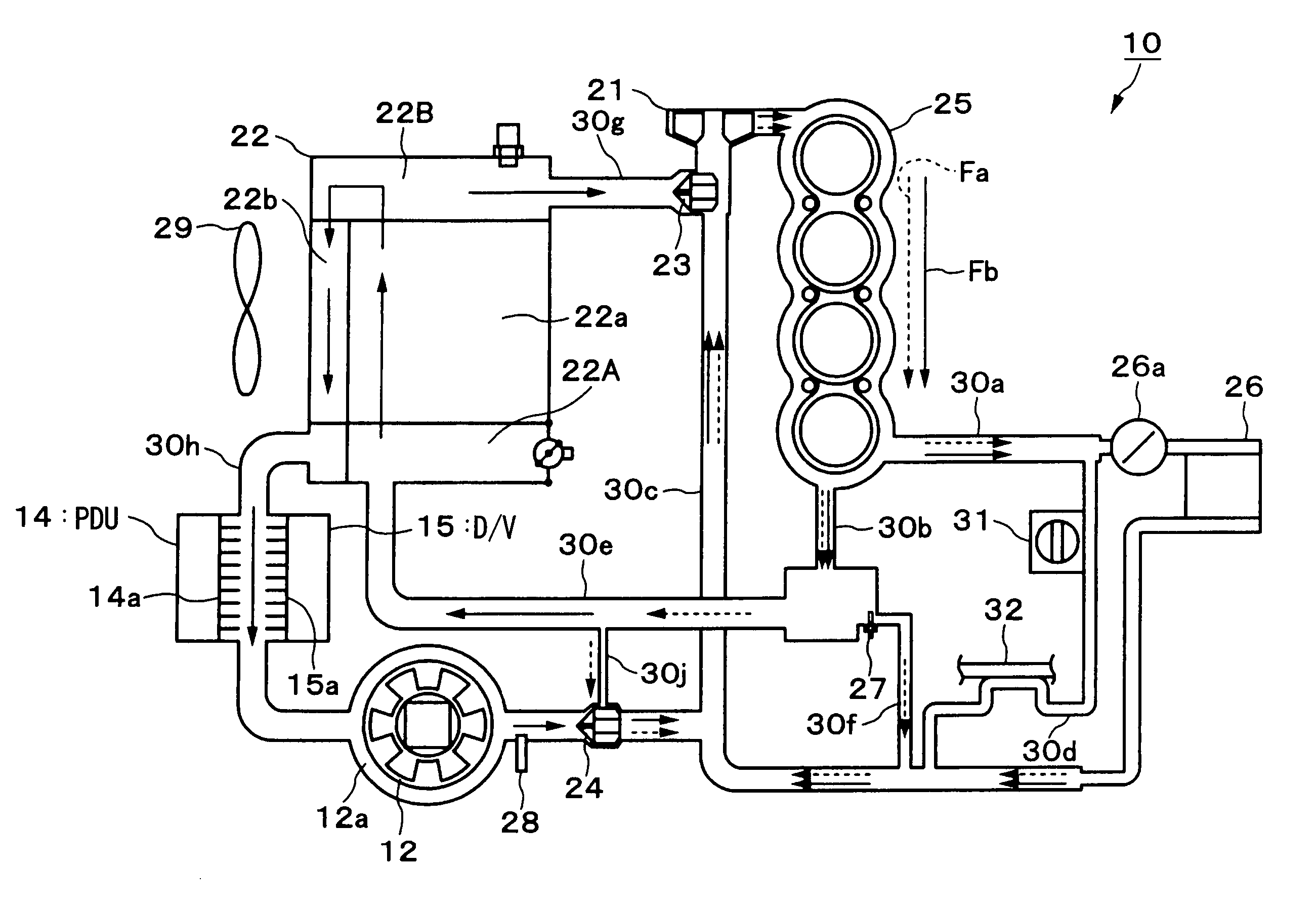
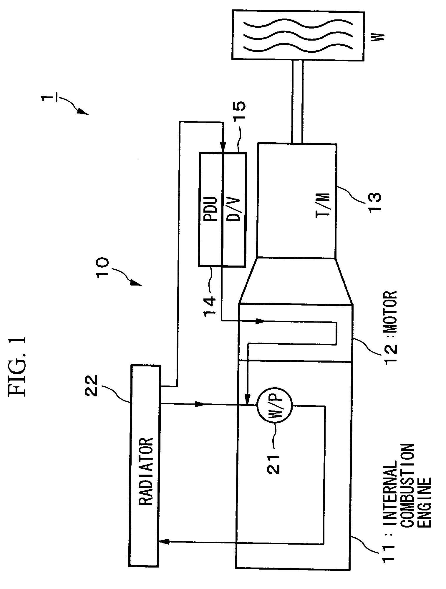
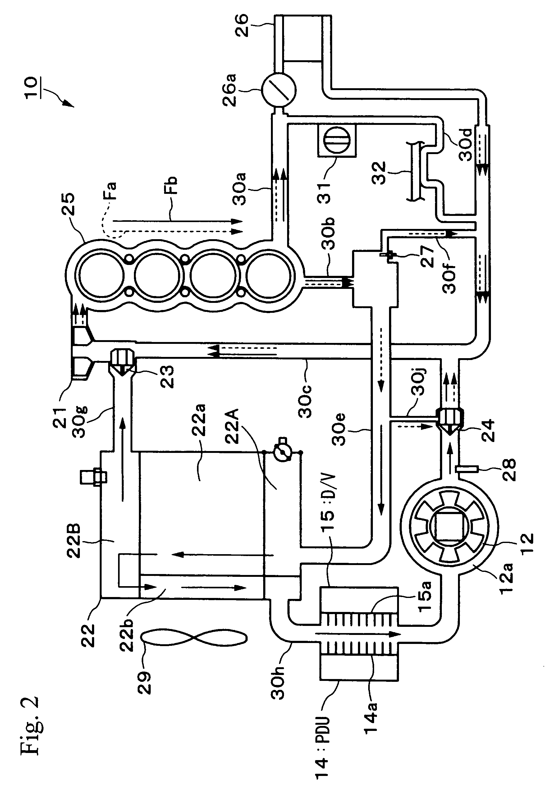
[0041]Hereunder, a first embodiment of a cooling apparatus for a hybrid vehicle of the present invention will be described, with reference to the appended drawings.

[0042]A cooling apparatus for a hybrid vehicle 10 according to the first embodiment of the present invention, as for example shown in FIG. 1, is mounted in a hybrid vehicle 1 in which an internal combustion engine 11, a motor 12, and a transmission (T / M) 13 are connected in series. In this hybrid vehicle 1, for example the driving forces from both the internal combustion engine 11 and the propulsion motor 12, are transmitted to drive wheels W via the transmission (T / M) 13 such as a CVT, manual transmission or the like.

[0043]The motor 12 generates an auxiliary driving force which assists the driving force of the internal combustion engine 11 depending on the driving state of the hybrid vehicle 1. Furthermore, at the time of deceleration of the hybrid vehicle 1, when a driving force is transmitted to the motor 12 side from ...


PUM


Abstract

In order to appropriately control the temperature state of multiple equipment having differing management temperatures, while preventing complication of the apparatus structure, a cooling apparatus for a hybrid vehicle is provided with a seventh flow path 30g which flows coolant which has flowed only through a main flow path 22a of a radiator 22 to a water jacket 25 via a first thermostat 23 which has an induction temperature set relatively high; an eighth flow path 30h which flows coolant which has flowed through the main flow path 22a and a sub flow path 22b of the radiator 22 to the water jacket 25 via a second thermostat 24 which has an induction temperature set relatively low, and also supplies the coolant to a PDU14 and a downverter 15; and a bypass flow path 30j which connects a fifth flow path 30e which supplies coolant discharged from the water jacket 25 to the radiator 22, and a position of the eighth flow path 30h on a downstream side of the second thermostat 24.

Description

BACKGROUND OF THE INVENTION[0001]Priority is claimed on Japanese Patent Application No. 2003-045881, filed Feb. 24, 2003, the content of which is incorporated herein by reference.FIELD OF THE INVENTION[0002]This invention relates to a cooling apparatus for a hybrid vehicle driven by an internal combustion engine and a motor.DESCRIPTION OF THE RELATED ART[0003]Heretofore, for a radiator installed in a cooling circuit which flows coolant for cooling the engine, there is known an apparatus (for example, see Patent Literature 1) in which there is provided an additional flow path in addition to the main flow path within the radiator, through which one part of the coolant which has flowed within this radiator is diverted so as to flow through the radiator a second time, and which controls the temperature of working fluid such as ATF (Automatic Transmission Fluid) or the like, by means of coolant which has flowed through this additional flow path, that is, the coolant which is of a relativ...

Claims


Application Information

Patent Timeline
Patent Type & Authority Patents(United States)
IPC IPC(8): B60K6/02B60K6/22B60K6/485B60K6/54B60K11/02F01P3/20F01P7/16
CPCB60K6/22B60K6/485B60K6/54B60K11/02F01P3/20F01P7/165B60K2001/003Y02T10/6226F01P7/167F01P2025/50F01P2050/24F01P2050/30F01P2060/08Y02T10/62
Inventor FUKUDA, KENJIKIMURA, HIDEOHOTTA, NAOKIABE, NORIYUKIHASEBE, TETSUYASAITO, OSAMU
Owner HONDA MOTOR CO LTD
Learn More