Charged particle beamlet exposure system

a beamlet exposure and charge technology, applied in the field of chargeable particle optical systems, can solve the problems of increasing the cost of masks currently used for providing patterns, limiting the throughput of current maskless lithography systems, and affecting the accuracy of the beamlet exposure. achieve the effect of improving speed and stability

Inactive Publication Date: 2006-08-01
ASML NETHERLANDS BV
View PDF6 Cites 264 Cited by
  • Summary
  • Abstract
  • Description
  • Claims
  • Application Information

AI Technical Summary

Benefits of technology

[0011]It is the purpose of the present device to provide a maskless charged particle lithography system with arrangements to overcome the aforementioned problems encountered in charged particle optical systems, in particular is such systems used in the present maskless charged particle beam lithography systems, both single and multi-beam. It thus seeks to provide a charged particle optical system which has an improved speed and stability.
[0017]It was found that imaging a previous aperture or aperture array on a subsequent aperture or aperture array makes the system more stable with respect to alignment, and reduces heat load by shielding or blocking.

Problems solved by technology

Consequently the feature sizes decrease rapidly resulting in a sharp increase of the costs of a masks currently used for providing a pattern.
Since a mask is a highly efficient way to store a pattern, the amount of raw data describing such a pattern is enormous.
Current maskless lithography systems are limited in throughput, i.e. the number of processed wafers per hour.
This feature limits the use of these systems in present day semiconductor element processing lines.
The data supply to the sources becomes a problem when the data rate increases: Each individual source has a settling time that is source-dependent and becomes too large easily.
Especially in compact multibeam designs, misalignment of the consecutive components (lenses, apertures etc.) of the system or a slight change of the position of the beam by for instance external electromagnetic fields, for instance resulting from charging of surfaces or irregularities on charged surfaces, results in dose variations.
As a result of the dose variation the control of the critical dimensions of the features to be patterned is no longer guaranteed.
This approach has several drawbacks, which become pertinent when high speed and extreme dose stability are required.
Furthermore, the amount of deflection needed to completely block a beamlet will increase (see drawings for an explanation), which will reduce the speed and thus throughput of such a system.

Method used


Image

  • Charged particle beamlet exposure system
  • Charged particle beamlet exposure system
  • Charged particle beamlet exposure system

Examples


Embodiment Construction

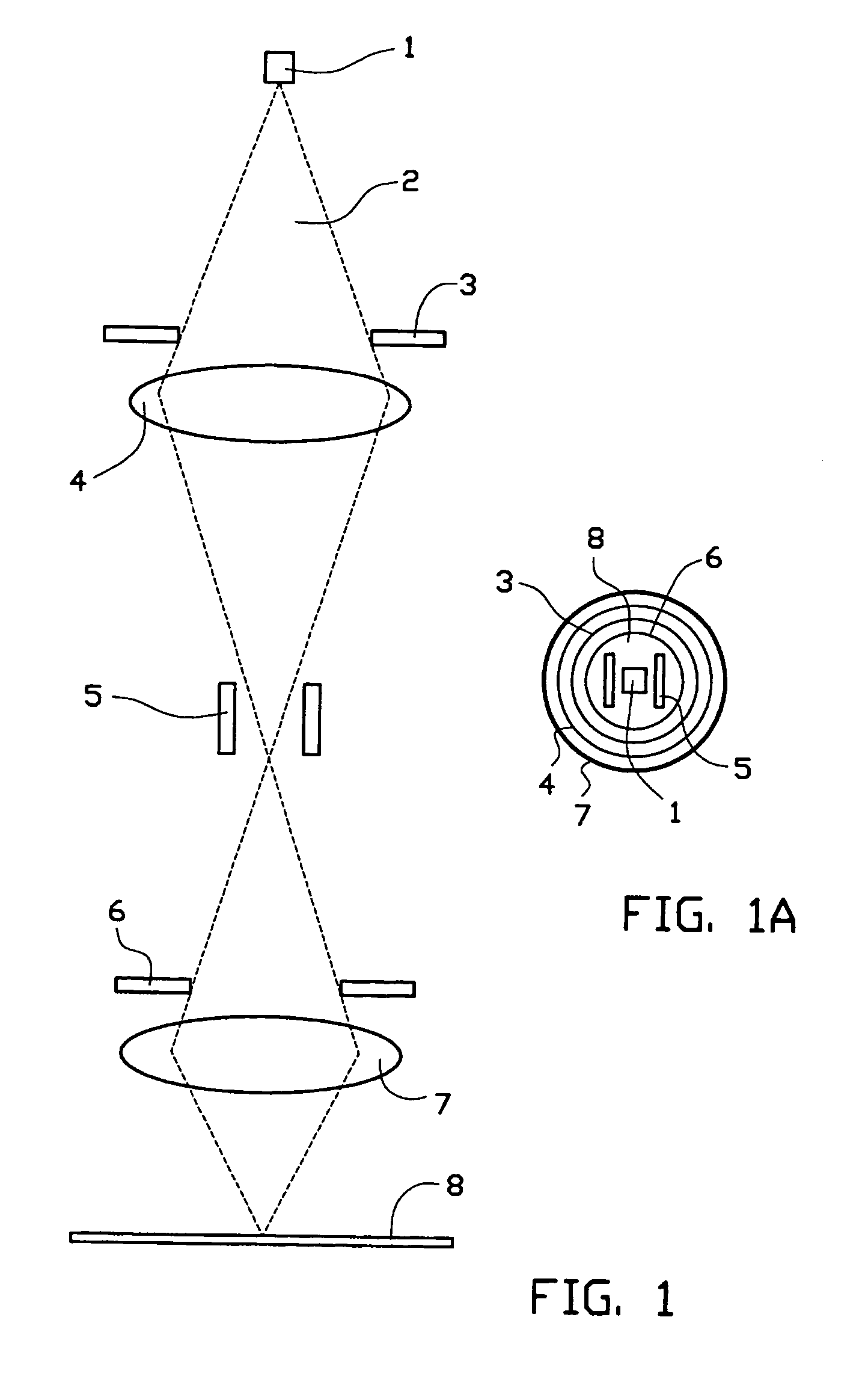
[0044]FIG. 1 shows cross section along the optical axis of a charged particle beam exposure apparatus comprising a charged particle source, two apertures, two lenses and one electrostatic deflector. The FIG. 1A shows a top-view of FIG. 1

[0045]The source 1 emits a diverging charged particle beam 2. The first aperture 3, being substantially round, limits the opening angle of the beam impinging on the first lens 4. Additionally it takes heat away from the system, thereby enhancing the performance of the first lens 4. Said lens 4 focuses the beam substantially on the plane of the electrostatic deflector 5. Upon the reception of control signals, the deflector 5 deflects the passing charged particle beam. The second aperture 6, being substantially round, can have several purposes. First of all it may limit the opening angle of the beam falling on the second lens 7. Secondly it blocks the beam when deflected by the electrostatic deflector 5. When the beam is transmitted through the second ...


PUM


Abstract

The invention relates to a charged-particle-optical system for a charged particle beam exposure apparatus, said system comprising:a first aperture means comprising at least a first substantially round aperture for partially shielding an emitted charged particle beam for forming a charged particle beamlet;a lens system comprising at least one lens for focussing a charged particle beamlet from said first aperture within or in the vicinity of an image focal plane of said lens;a deflector means, substantially located in said image focal plane, comprising at least one beamlet deflector for the deflection of a passing charged particle beamlet upon the reception of a control signal, anda second aperture means comprising at least one second substantially round aperture positioned in the conjugate plane of the first aperture, and said second aperture being aligned with said first aperture and said beamlet deflector for blocking said charged particle beamlet upon deflection by said beamlet deflector and to transmit it otherwise.

Description

[0001]This application claims the benefit of U.S. Provisional Application No. 60 / 473,810, filed May 28, 2003.BACKGROUND[0002]This invention relates to charged particle optical system for a charged particle exposure apparatus, in particular a maskless lithography system using charged particles.[0003]The development of lithography systems in particular is driven by Moore's law i.e. the number of transistors per unit area doubles every 18 months. Consequently the feature sizes decrease rapidly resulting in a sharp increase of the costs of a masks currently used for providing a pattern. To avoid the increasing mask costs several maskless lithography concepts are under development. In these concepts the pattern is represented by pattern data. Since a mask is a highly efficient way to store a pattern, the amount of raw data describing such a pattern is enormous.[0004]Current maskless lithography systems are limited in throughput, i.e. the number of processed wafers per hour. This feature ...

Claims


Application Information

Patent Timeline
Patent Type & Authority Patents(United States)
IPC IPC(8): H01J37/04H01J37/10H01J37/08H01J37/30H01J37/317
CPCB82Y10/00B82Y40/00H01J37/045H01J37/3007H01J37/3174H01J37/3177H01J2237/1501H01J2237/0435H01J2237/045H01J2237/0453H01J2237/0492H01L21/0274
Inventor WIELAND, MARCO JAN-JACOKRUIT, PIETER
Owner ASML NETHERLANDS BV
Why Eureka
Try Eureka