Laser apparatus, exposure apparatus and method

a technology of exposure apparatus and laser, which is applied in the field of laser apparatus, can solve the problems of inability to turn a wavelength spectral bandwidth, inability to maintain pulse energy at a desired value, and difficulty in chromatic aberration correction

Inactive Publication Date: 2006-08-01
CANON KK
View PDF18 Cites 7 Cited by
  • Summary
  • Abstract
  • Description
  • Claims
  • Application Information

AI Technical Summary

Benefits of technology

[0011]Accordingly, it is an exemplified object of the present invention to provide a laser apparatus, and an exposure apparatus and method, which indirectly detect a change in an oscillation wavelength and wavelength spectral bandwidth of a laser beam, and maintain predetermined optical performance.

Problems solved by technology

Optical elements that efficiently transmit light in such a wavelength range (i.e., in the ultraviolet region) are limited to certain glass materials such as synthetic quartz, calcium fluoride, etc., and thus it is difficult to correct chromatic aberration.
On the other hand, in using the F2 laser as an exposure light source, it is impossible to turn a wavelength spectral bandwidth into a narrowband or to provide the wavelength control for technical reasons: including multiple oscillation spectra existing in the neighborhood of 157 nm; its wavelength spectral bandwidth in a spontaneous oscillation state as much as about 1 pm, i.e., narrower than the KrF excimer laser and the ArF excimer laser; difficult turning of the laser beam into a narrower band since the performance of an optical element used for a wavelength bandwidth of 157 nm has not been satisfactory enough to be put into practical use, difficult measurement of a wavelength and a wavelength spectral bandwidth with high precision inside a laser apparatus, and so on.
As a result, the pulse energy cannot be maintained at a desired value even with the increased voltage to be applied between the electrodes rises and gas injection, because.
If they exceed, e.g., wavelength stability and a tolerance of the wavelength spectral bandwidth required by an exposure system, it becomes difficult to achieve desired resolution required for the exposure apparatus.
Moreover, when the F2 laser is used, it is difficult to directly confirm whether or not the laser beam exhibits its desired performance during exposure, because the measurement of a wavelength is technically very difficult in a laser apparatus with high accuracy.
The direct confirmation of the oscillation wavelength, if any, would clearly give an adverse impact onto the productivity of the exposure apparatus in running cost and maintenance frequency in light of the current durability of a current optical element.
A similar problem arises when a laser that oscillates in a wavelength shorter than the F2 laser is used as a light source.

Method used


Image

  • Laser apparatus, exposure apparatus and method
  • Laser apparatus, exposure apparatus and method
  • Laser apparatus, exposure apparatus and method

Examples


Embodiment Construction

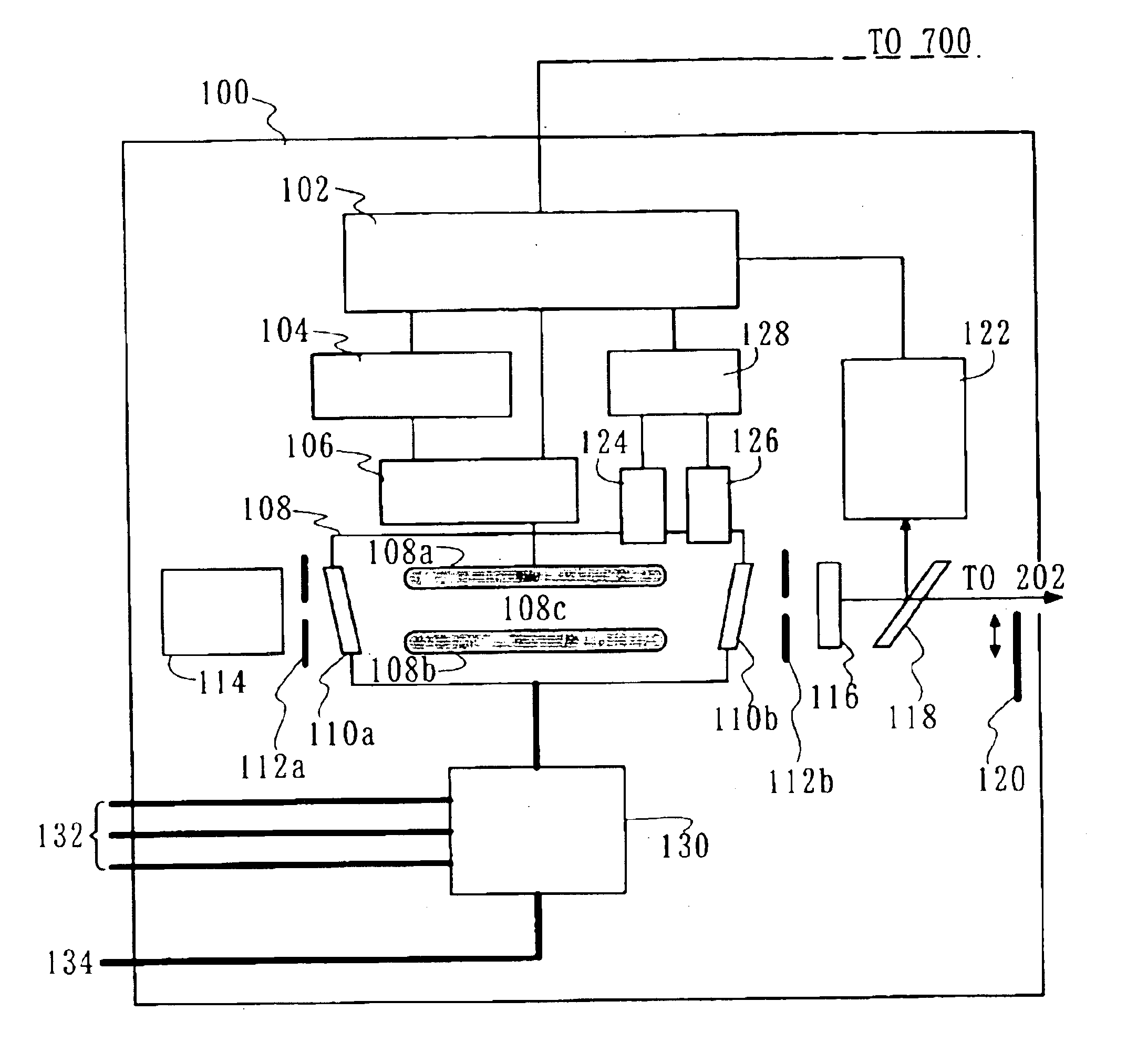
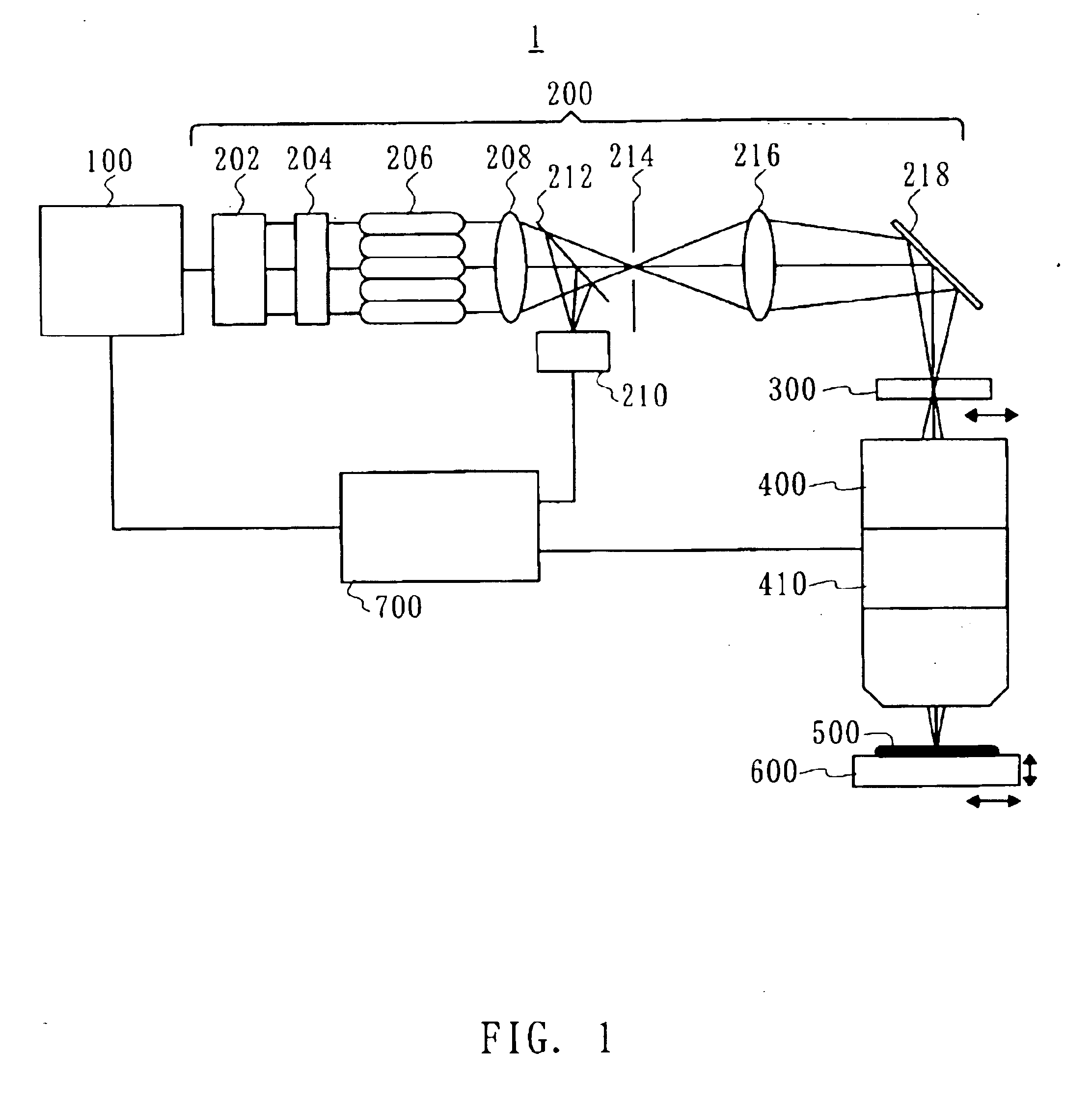
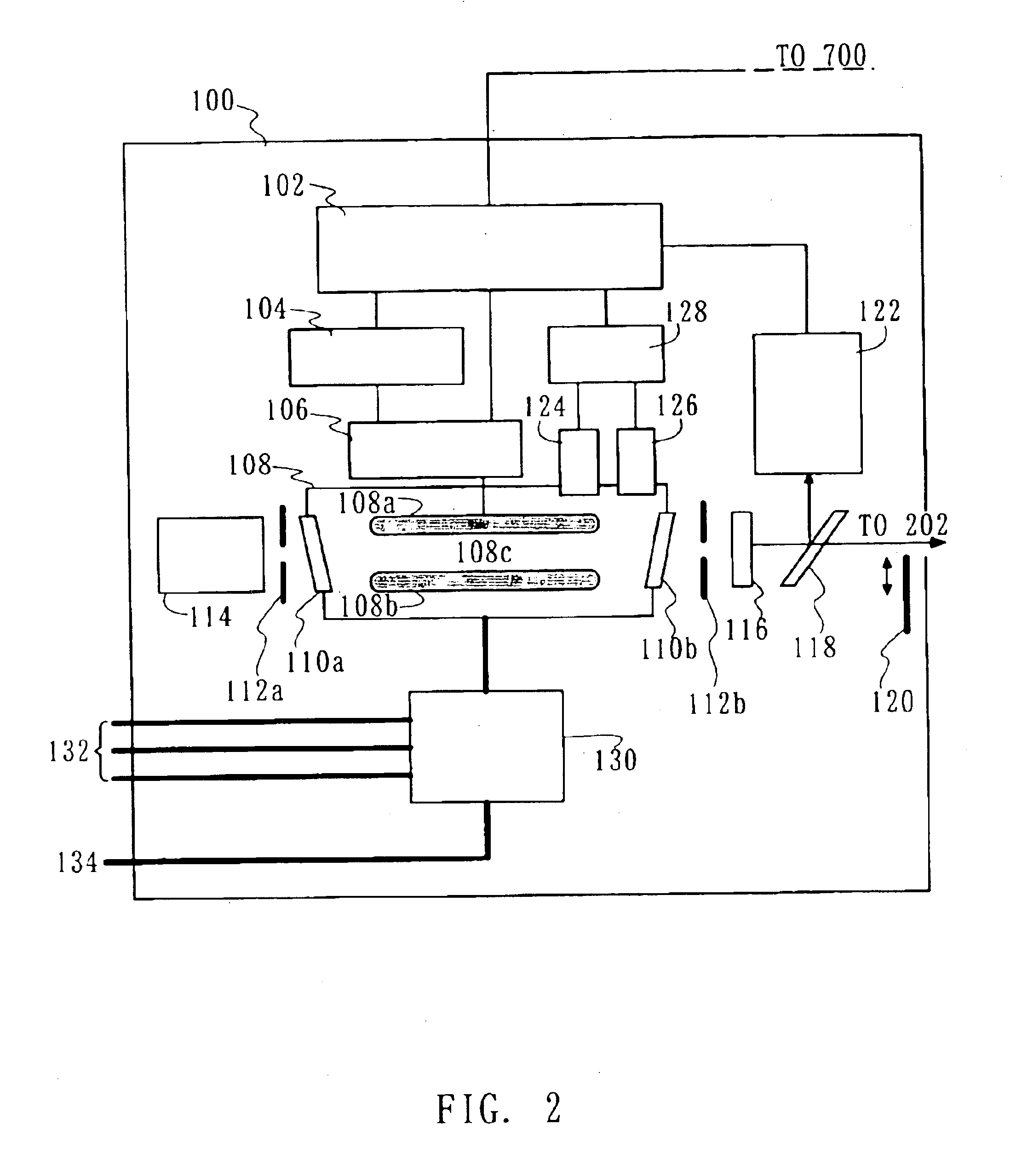
[0032]Referring now to accompanying drawings, a description will be given of an exposure apparatus 1 and a laser apparatus 100 as aspects of the present invention. However, the present invention is not limited to these embodiments, and each element may be replaced within a scope of this invention. Here, FIG. 1 is a schematic block diagram of the exposure apparatus 1 as one aspect of the present invention. As shown in FIG. 1, the inventive exposure apparatus 1 includes the laser apparatus 100, an illumination optical system 200, a mask 300, a projection optical system 400, a plate 500, a stage 600, and a controller 700.

[0033]The exposure apparatus 1 is a projection exposure apparatus that exposes onto the plate 500 a circuit pattern created on the mask 300, e.g., in a step-and-repeat or a step-and-scan manner. Such an exposure apparatus is suitable for a submicron or quarter-micron lithography process, and this embodiment exemplarily describes a step-and-scan exposure apparatus (whic...


PUM


Abstract

There is to provide a laser apparatus that emits a laser beam by exciting gas enclosed in a chamber, including a gas characteristic detecting mechanism for detecting a characteristic of the gas in the chamber, and a calculation mechanism for calculating an oscillation wavelength and/or a wavelength spectral bandwidth of the laser beam based on a detected result by the gas characteristic detecting mechanism.

Description

BACKGROUND OF THE INVENTION[0001]The present invention relates generally to laser apparatuses, and more particularly to a laser apparatus in an exposure apparatus that illuminates a mask or reticle (these terms are used interchangeably in this application) which forms a pattern for use with a lithography process for fabricating semiconductor elements, liquid crystal display devices (LCD), image pick-up devices (such as CCDs, etc.), thin-film magnetic heads, and the like.[0002]Along with recent demands on smaller and lower profile electronic devices, fine semiconductor devices to be mounted onto these electronic devices have been increasingly in demand. As a transfer (lithography) method for fabricating semiconductor devices, a projection exposure apparatus has been used conventionally.[0003]A critical dimension (or resolution) transferable by a projection exposure apparatus is in proportion to the wavelength of light to be used for exposure. Therefore, in recent years, the exposure ...

Claims


Application Information

Patent Timeline
Patent Type & Authority Patents(United States)
IPC IPC(8): H01S3/22H01S3/223H01S3/13H01S3/134H01S3/225
CPCH01S3/225H01S3/134H01S3/1305H01L21/027
Inventor NAGAI, YOSHIYUKI
Owner CANON KK
Why Eureka
Try Eureka