High speed analyzer using near infrared radiation transmitted through thick samples of optically dense materials

a technology of optical density and analyzer, which is applied in the direction of optical radiation measurement, instruments, spectrometry/spectrophotometry/monochromator, etc., to achieve the effects of high sensitivity, low intensity radiation level can be measured quickly, and medium resolution

Inactive Publication Date: 2006-08-08
LEADER TECH
View PDF15 Cites 13 Cited by
  • Summary
  • Abstract
  • Description
  • Claims
  • Application Information

AI Technical Summary

Benefits of technology

[0086]The present invention relates to means for measuring in relatively short periods of time constituents in optically dense materials using the spectra of near infrared radiation transmitted through even relatively thick samples of the material while the material is either stationary or flowing. The invention uses a broadband incandescent intensity controlled light source combined with collimating optics to transmit a parallel beam of light through the material under test. The light transmitted through the material is then collected by a focusing lens and imaged onto a rectangular entrance slit of a special purpose spectrometer. This spectrometer has no moving parts and employs a fixed diffraction grating to physically spread the image of the entrance slit into a continuous range of wavelengths. A portion of that diffracted slit image covering a portion of the near infrared range is imaged onto an array of individual rectangular photodiodes. The slit dimensions are the same as the individual photodiode dimensions. The slit and photodiodes are oriented in the same direction with the long side of the slit parallel to the long sides of the individual photodiodes. By using arrays with a relatively small number of large active area photodiodes, high sensitivity is achieved and low intensity radiation levels can be measured quickly. By using a relatively narrow spectral range, medium resolution can be achieved. The outputs of each photodiode, or the outputs of a selected number of the photodiodes are fed into current to voltage converters: either resistive (instantaneous) or the preferred capacitive (integrating). Thus the outputs of all photodiodes are measured in parallel. This parallel operation also reduces the time to acquire the spectra. After the spectra are acquired, they are operated on by models developed to predict the percentages of various constituents in the material. These models are pre-calibrated using spectra obtained from materials of known concentrations and developed using chemometric, neural net, and / or genetic algorithms.

Problems solved by technology

There are, however, disadvantages to reflectance analyzers.
Some of the major disadvantages are:1. Reflectance spectrometers only measure a thin layer of the surface of the substance being measured.
This is a disadvantage if the material is not homogeneous.
This problem is most severe when granular material such as grain is being measured.
For reflectance mode spectrometers placement of the reference material inside the sample chamber is difficult or expensive to do.
In spite of the progress that has been made in the development of NIR analyzers and their many different uses, there are a number of deficiencies that prevent wider application of the technology.
1. NIR Energy Generation: Tungsten Halogen Lamps are preferredLED's in general have insufficient light output and spectral range
2. Spectral Separation: Fixed Diffraction Gratings are preferredScanning gratings, rotating filters, AOTF and FT-NIR are too slowScanning gratings, rotating filters, and FT-NIR have moving parts, and are vibration sensitiveFilters are not temperature stable and temperature stabilization is expensive FT-NIR and AOTF are expensive.
3. NIR Energy Delivery to Substance: Collimating Optics is preferredFiber Optics reduces the intensity too much.
4. NIR Energy Collection From Substance: Collection of Transmitted Energy through focusing optics is preferredReflected Energy is susceptible to dust and uses moving parts to measure energy reflected off of reference materialFiber Optics reduces intensity too much
5. Measurement of Collected NIR Energy. No Suitable ChoiceSingle Detector is too slow and requires moving parts. Wavelengths have to be scanned which is too slow, requires moving parts, and is subject to vibration.Detector Array (DA) with Serial Output: is too slow as output of array has to be scanned serially. The elements of typical diode arrays are too small so that outputs for low level intensity signals are too low.The detector type used: Silicon is preferredPhotomultipliers are too expensiveInGaAs photodiode is too expensive, insensitive and requires temperature stabilizationPbS photoresistor is too expensive, insensitive and requires temperature stabilization
There are no commercially available spectrometers that can be used to construct an NIR analyzer with the requirements specified above.
But these suffer from a number of drawbacks.
This means that the power incident on each photodiode is very low.
Thus low intensity signals that would come from NIR energy transmitted through relatively thick samples of optically dense material would take a long time to acquire if they could be acquired at all.
In addition the dynamic range of the instrument is limited and would not permit acquisition of a reference signal that is 1000× greater or more in intensity than the sample signal.
Finally, most of the small medium priced diode array based spectrometers are designed only for fiber optic inputs, decreasing the signal strength even further.
In summary, the diode array based spectrometers available today are too slow, have too little dynamic range, and do not collect enough energy to meet the specified requirements.

Method used


Image

  • High speed analyzer using near infrared radiation transmitted through thick samples of optically dense materials
  • High speed analyzer using near infrared radiation transmitted through thick samples of optically dense materials
  • High speed analyzer using near infrared radiation transmitted through thick samples of optically dense materials

Examples


Embodiment Construction

[0095]The following description of the present invention applies to its preferred embodiment. Those of ordinary skill in the art will understand that the present invention, however, is not limited to the described embodiment.

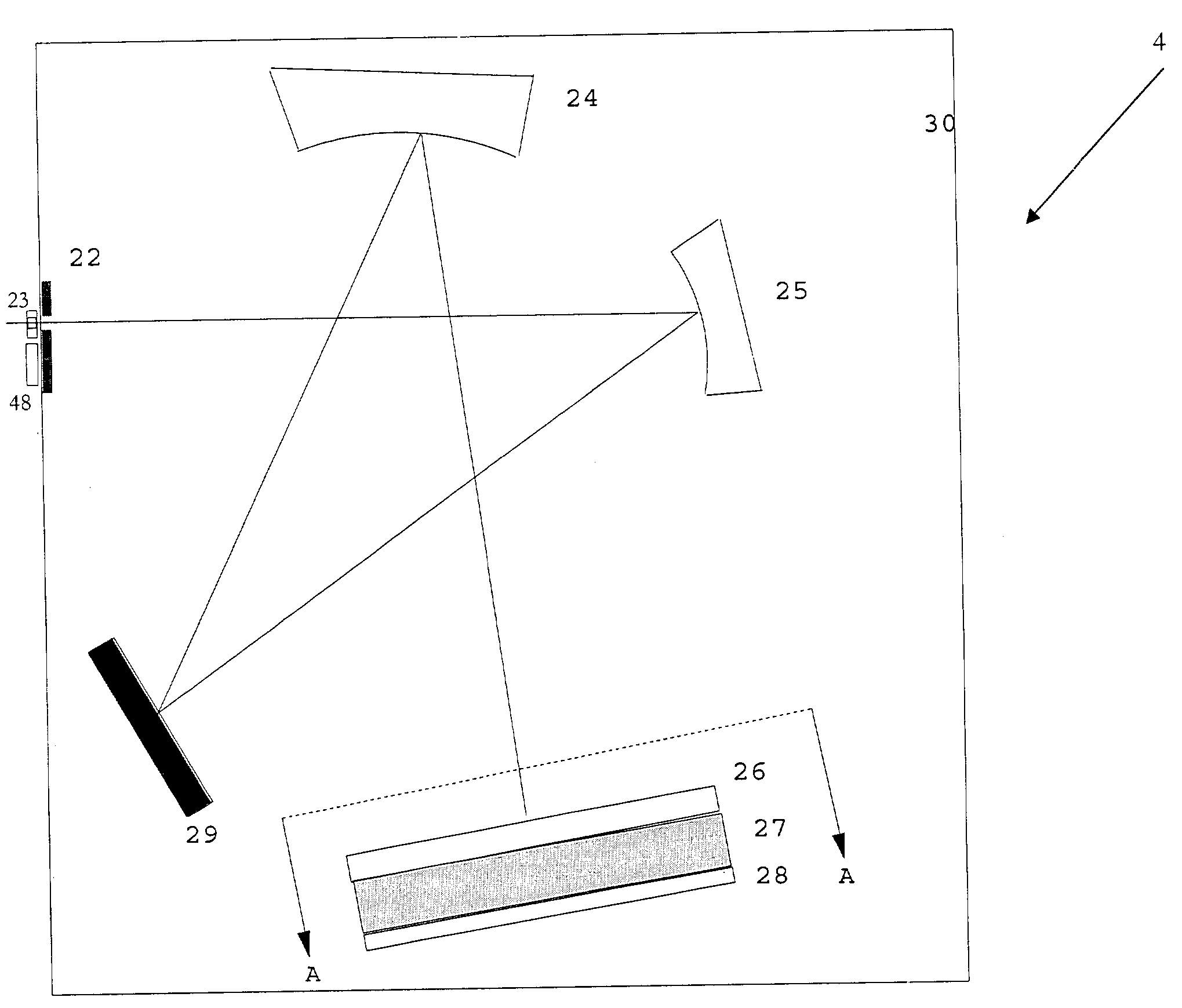
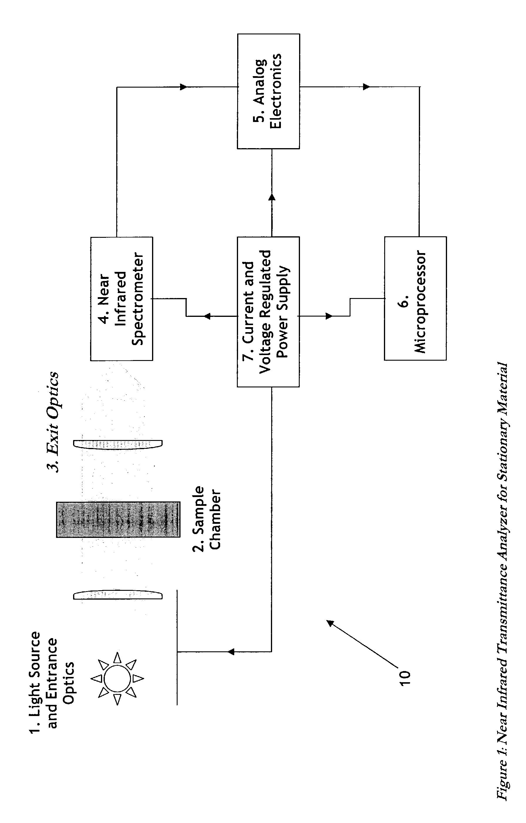
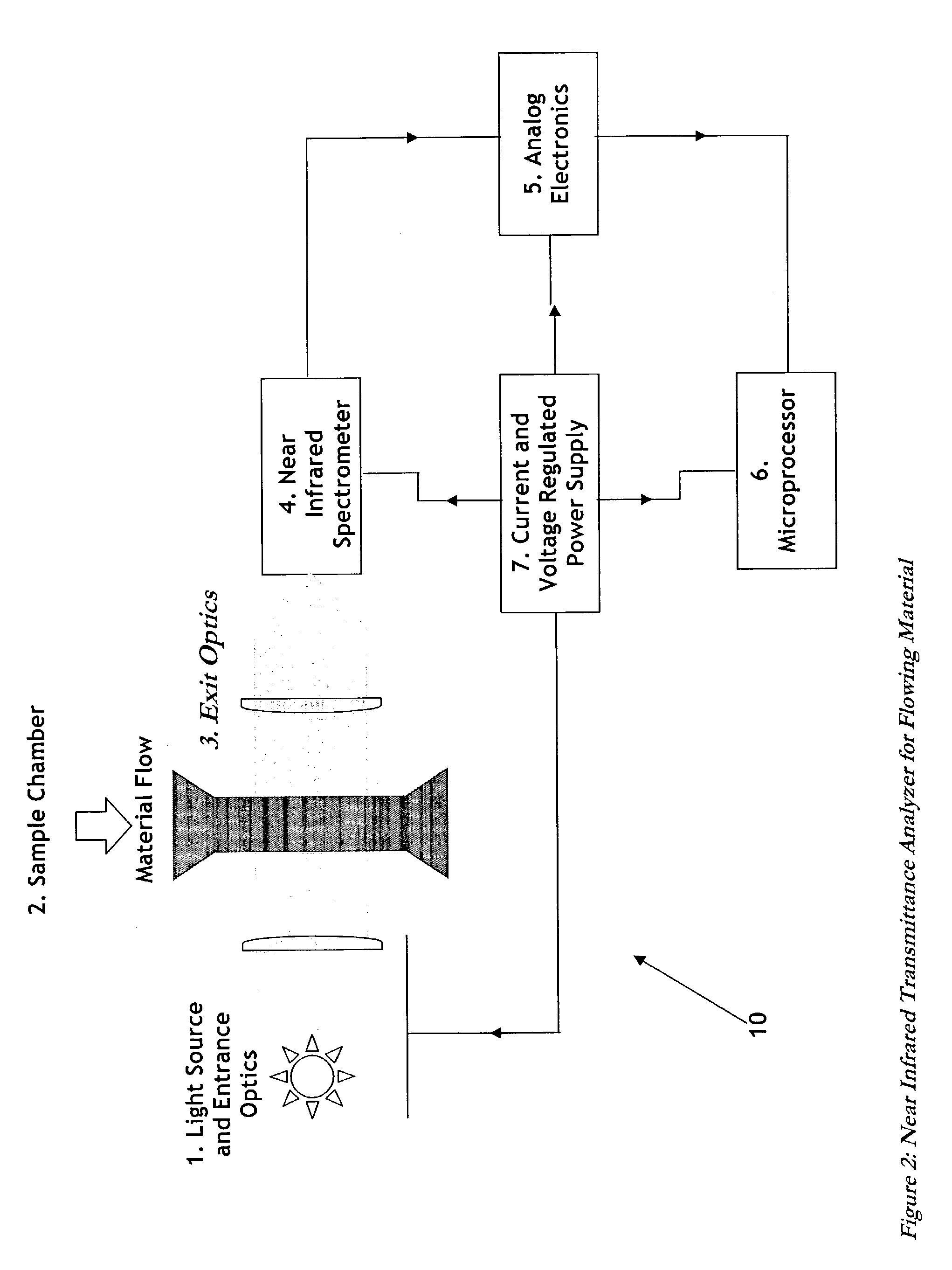
[0096]FIGS. 1–2 show a block diagram of the NIR analyzer 10 for use on stationary and flowable material respectively. Seven major components of the analyzer 10 are identified in FIGS. 1–2. These components and their functions are:[0097]Light source and entrance optics, comprising an incandescent light source 1 that generates a broad spectrum of radiant energy including a continuous component in the selected near infrared range. Part of this radiant energy is collected by a lens and collimated into an approximately parallel beam. This beam is transmitted through a transparent window 17 into the sample chamber 2 holding the material;[0098]Sample chamber 2 is a fixed rectangular chamber for holding the material whose constituents are to be measured, with the transp...


PUM

PropertyMeasurementUnit
near infrared wavelengthsaaaaaaaaaa
wavelengthsaaaaaaaaaa

Abstract

The present invention relates to an instrument for measuring in relatively short periods of time concentrations of constituents in optically dense materials using the spectra near infrared radiation transmitted through thick samples of the material while the material is either stationary or flowing. The invention uses a broadband incandescent intensity stabilized light source combined with collimating optics to transmit a parallel beam of light through the material under test. The light transmitted through the material is then collected by a focusing lens and imaged onto a rectangular entrance slit of a special purpose spectrometer. This spectrometer has no moving parts and employs a fixed diffraction grating to physically spread the image of the entrance slit into a continuous range of wavelengths. A portion of the diffracted slit images covering the selected portion of the near infrared range is focused onto an array of individual rectangular photodiodes. By using relatively large area photodiodes and a relatively small number of photodiodes, high sensitivity is achieved and low intensity radiation levels can be measured quickly. By using a relatively narrow spectral range, medium resolution can be achieved. The outputs of each photodiode, or the outputs of a selected number of the photodiodes, are fed into current to voltage converters: either resistive (instantaneous) or preferred capacitive (integrating). Thus the outputs of all photodiodes are measured in parallel, which reduces the time to acquire the spectra. The gain of these current to voltage converters is programmable so that both high intensity and low intensity near infrared radiation levels can be measured without reducing the intensity of the radiation incident on the material under test and thereby eliminating the need for moving parts in the spectrometer. After the spectra are acquired, they are operated on by models developed to predict the percentages of various constituents in the material. These models are pre-calibrated using spectra obtained from materials of known concentrations and developed using chemometric, neural net, and / or genetic algorithms.

Description

RELATED APPLICATIONS[0001]The present application claims priority to U.S. Provisional Patent Application No. 60 / 365,698, filed on Mar. 20, 2002, and incorporates the same by reference thereto.FIELD OF THE INVENTION[0002]The present invention relates to means for measuring in relatively short periods of time constituents in optically dense materials using medium resolution spectra in the near infrared range transmitted through thick samples of the material while the material is either stationary or flowing. More particularly, though not exclusively, the present invention relates to a method and apparatus using a specific type of near infrared spectrometer developed for this purpose in combination with a spectral based model to measure percentages of the major constituents of stationary or flowing material such as grains, processed foods, pharmaceuticals, chemicals, and other industrial or agricultural products.BACKGROUND OF THE INVENTION[0003]The measurement of near infrared (NIR) sp...

Claims


Application Information

Patent Timeline
Patent Type & Authority Patents(United States)
IPC IPC(8): G01N21/35
CPCG01N21/359G01N21/3563
Inventor AMBUEL, JACK
Owner LEADER TECH
Why Eureka
Try Eureka