High frequency partial boost power factor correction control circuit and method

a power factor and control circuit technology, applied in the field of power factor correction circuits, can solve the problems of increasing the size of the circuit, not meeting the requirements of today's regulation requirements, and high costs

Inactive Publication Date: 2006-08-08
INTERNATIONAL RECTIFIER COEP
View PDF3 Cites 64 Cited by
  • Summary
  • Abstract
  • Description
  • Claims
  • Application Information

AI Technical Summary

Problems solved by technology

Because the inductor operates at the line frequency, the physical size and inductance size are normally very large, requiring high costs and increasing size of the circuit.
The input current waveform is smoothed, but typically does not meet today's regulation requirements.
Manufacturers use this method to smooth the input current which may satisfy some applicable regulation standards, in particular in Japan, but may not meet the strict IEC standard for the European markets.
Also the inductor operates at the line frequency and its physical size and inductance are still large, resulting in still high costs and circuit size.
However, even this circuit has drawbacks.
In particular, the high frequency PWM switching causes high switching losses, less efficiency and creates electromagnetic interference (EMI) noise and 100% PFC may be more than is necessary for many design applications.

Method used


Image

  • High frequency partial boost power factor correction control circuit and method
  • High frequency partial boost power factor correction control circuit and method
  • High frequency partial boost power factor correction control circuit and method

Examples


Embodiment Construction

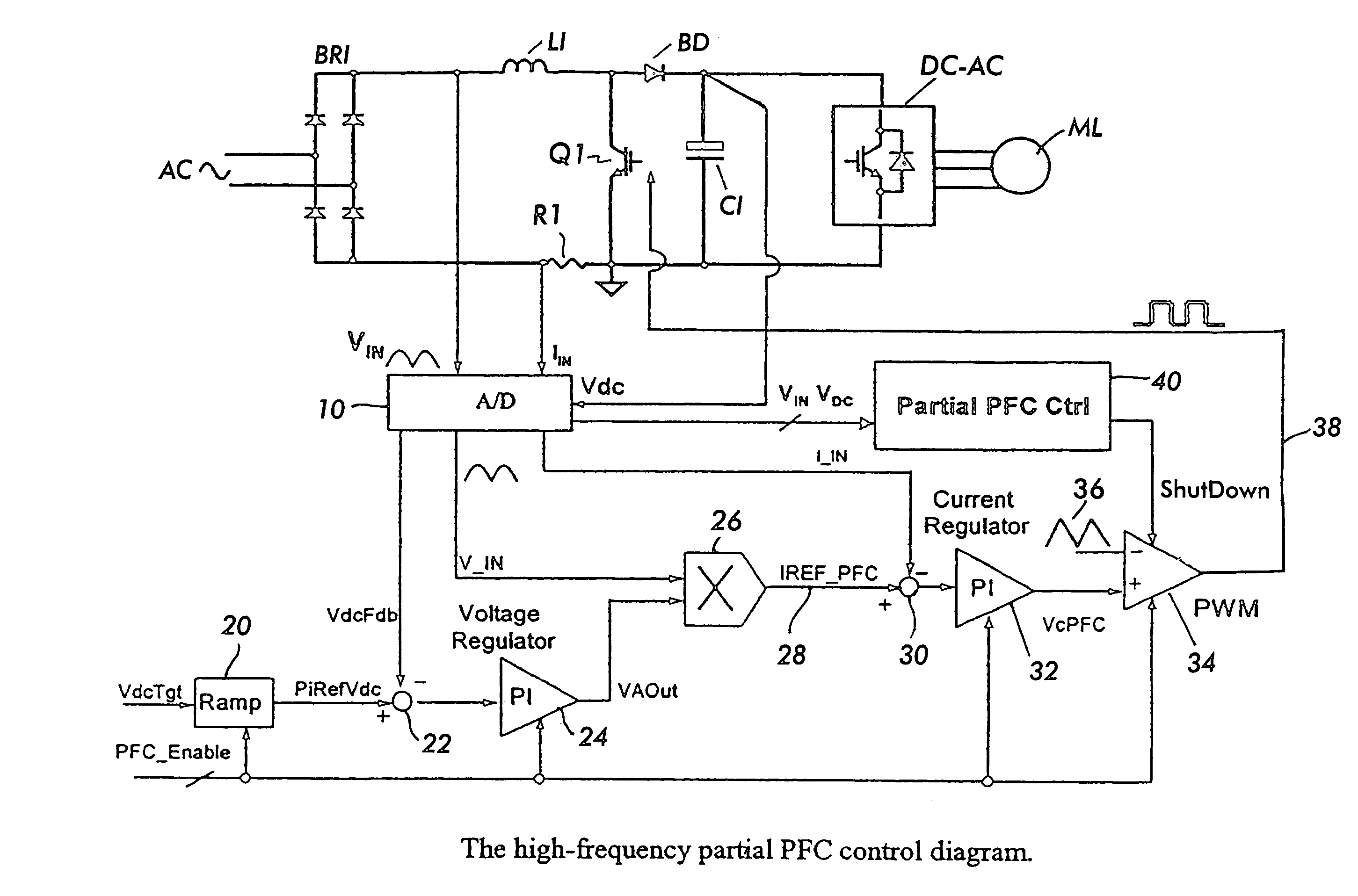
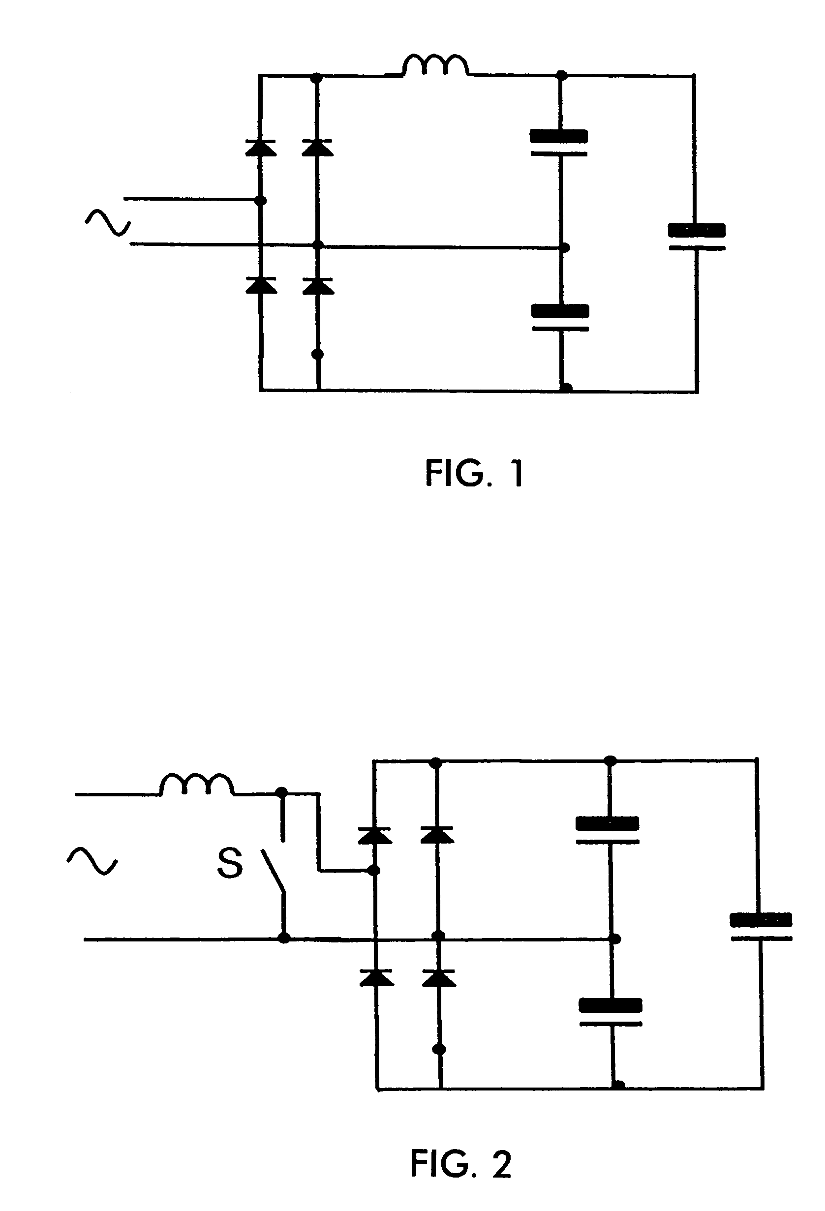
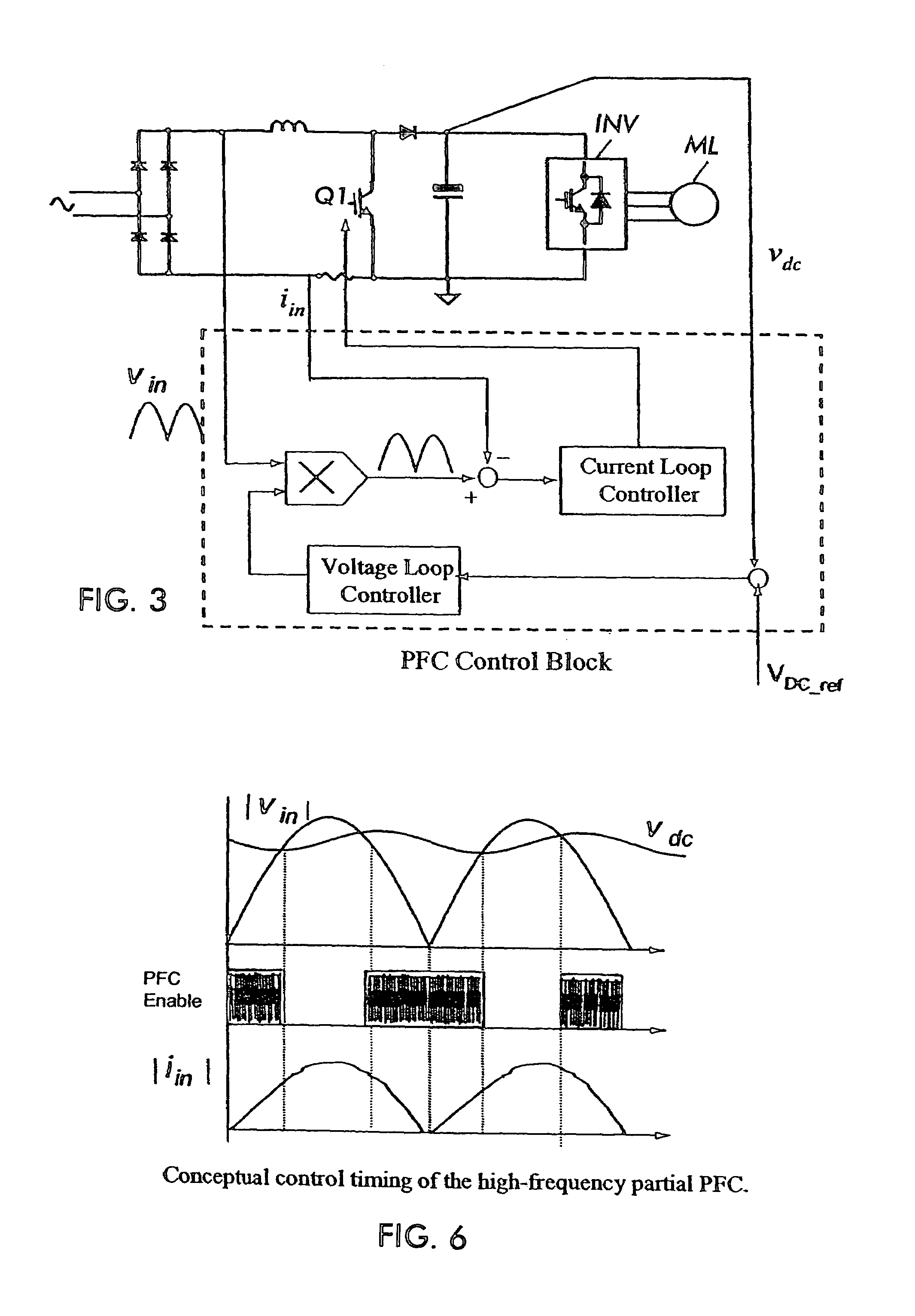
[0018]With reference again to the drawings, FIG. 5 shows the PFC circuit according to the present invention. The circuit includes a bridge rectifier BR1 fed from the AC supply. The rectified AC is provided to the boost inductor L1. A PFC switch Q1 is coupled in series with the inductor and across the output of the bridge rectifier after the inductor. The boost diode BD is coupled in series with the inductor L1 and the output capacitor C1 is coupled at shown at the output of the boost converter circuit in known fashion. The voltage across the capacitor C1 comprises the DC bus voltage which is provided to a load which might comprise, for example a DC to AC inverter driving a three phase motor load ML, for example.

[0019]The output of the DC bus VDC is provided to an A to D converter 10 which has as inputs the DC bus voltage VDC, the current IIN in the inductor L1 as sensed by a resistor RI or by other sensing means, as well as the rectified AC input voltage VIN. The A to D converter pr...


PUM


Abstract

A circuit for providing power factor correction comprising a boost converter circuit having a boost inductance and a power factor correction switch coupled in series with the boost inductance, the boost inductance and power factor correction switch being coupled across the output of a rectifier being supplied with AC power from an AC line, the boost converter circuit further comprising a boost diode coupled to a junction between the inductor and the switch, an output of the boost diode coupled to an output capacitor, a DC bus voltage being provided across the output capacitor, further comprising a control circuit receiving as inputs a rectified AC input voltage from the rectifier, a signal proportional to current through the inductor and the DC bus voltage across the capacitor, and wherein the control circuit provides a pulse width modulated signal to control the on time of the PFC switch, further comprising an enable / disable circuit receiving as inputs the rectified AC input voltage and the DC bus voltage, the circuit instantaneously comparing the rectified AC input voltage and the DC bus voltage and controlling the control circuit whereby the control circuit provides the pulse width modulated signal to control the PFC switch when the rectified AC input voltage is less than the DC bus voltage and disables the generation of the pulse width modulated signal to the PFC switch when the rectified AC input voltage is greater than DC bus voltage.

Description

CROSS-REFERENCE TO RELATED APPLICATIONS[0001]This application claims the benefit and priority of Provisional Application Ser. No. 60 / 583,752 filed Jun. 28, 2004, entitled A NEW HIGH-FREQUENCY PARTIAL BOOST POWER-FACTOR-CORRECTION CONTROL METHOD, the entire disclosure of which is hereby incorporated by reference herein.BACKGROUND OF THE INVENTION[0002]The present invention relates to power factor correction circuits, that is, circuits for reducing the distortion and harmonics generated in a power line feeding a power supply, and in particular a switched mode power supply. Power factor correction (PFC) circuits are utilized to reduce harmonics on power lines and in particular, make the circuit, including the attached load, appear to be a substantially purely resistive load. The aim of power factor correction circuits is to ensure that the AC voltage and current are substantially in phase. This improves efficiency and at the same time eliminates the generation of harmful harmonics.[000...

Claims


Application Information

Patent Timeline
Patent Type & Authority Patents(United States)
IPC IPC(8): G05F1/56G05F1/40H02M1/42
CPCH02M1/4225Y02B70/126Y02B70/10Y02P80/10
Inventor TAKAHASHI, TOSHILI, YONG
Owner INTERNATIONAL RECTIFIER COEP
Why Eureka
Try Eureka