

Method and an electrical device for efficient generation of multi-rate pseudo random noise (PN) sequence
- Summary
- Abstract
- Description
- Claims
- Application Information
AI Technical Summary
Benefits of technology
Problems solved by technology
Method used
Image

Examples
Embodiment Construction
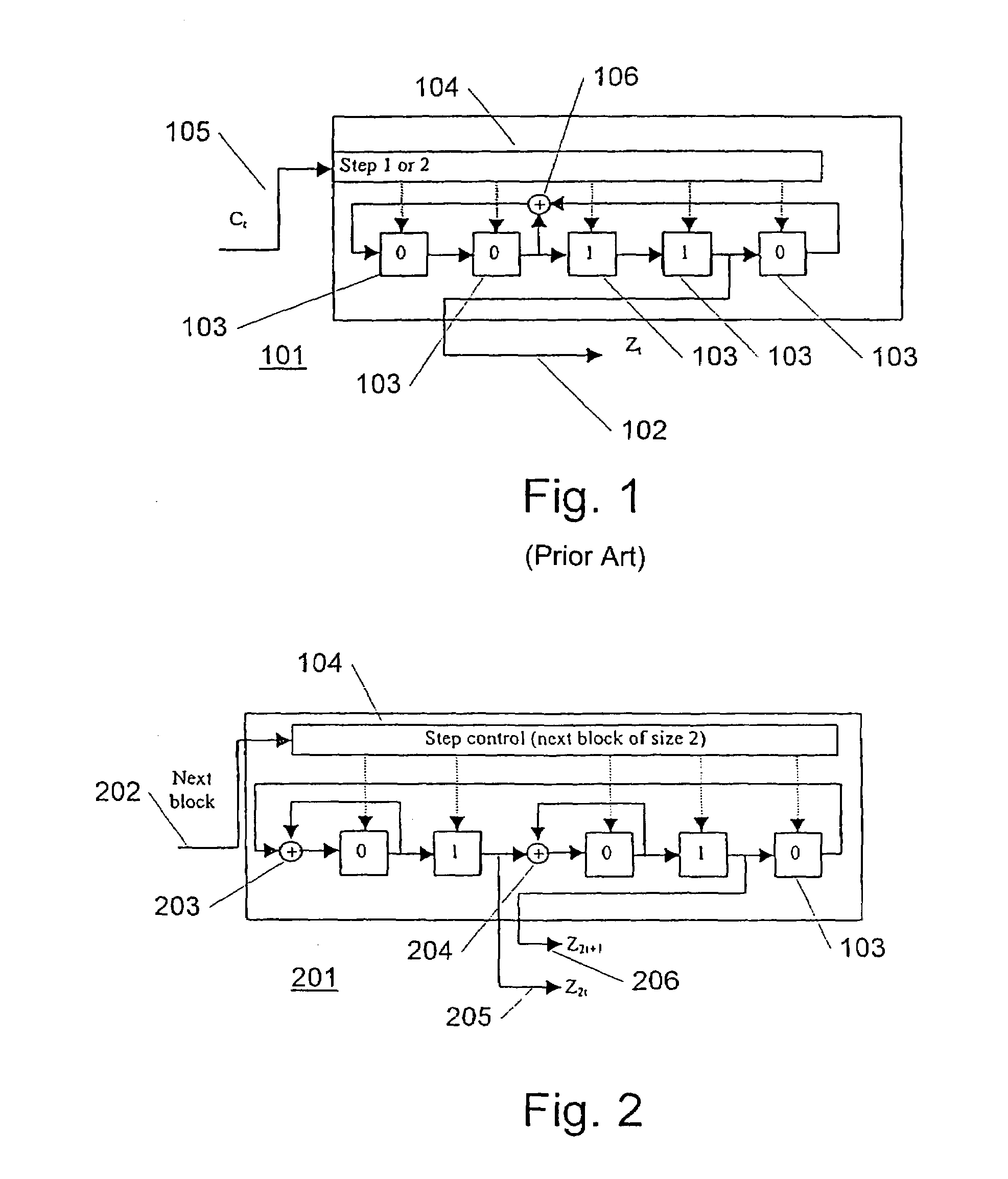
[0056]FIG. 1 illustrates a functional block diagram of a prior art (1,2)-step clock controlled m-sequence generator (101). This exemplary generator (101) outputs PN sequence symbols Zt (102). The generator (101) has L=5 delay elements (103) each connected to step control means (104) receiving a clock control signal Ct (105) where t denotes the time instants 0, 1, 2, . . . . In this way each element (103) is clock controlled by a sequence C=C0, C1, C2, C3, . . . , where each symbol represents the value 1 or 2, i.e. Ct ÎÎ {1,2}.
[0057]As will be seen, every value in the delay element (103) is shifted to the right at each time instant, except the value of the (from left to right) first element (103) which updates to the sum (without a carry) of the values of the second and the fifth delay elements (103) by an adding element (106).
[0058]If the m-sequence generator (101) steps once every time instant, the generator (101) will produce the simple sequence X=X0, X1, X2, X3, . . . . With the ...
PUM
 Abstract
Description
Claims
Application Information