Control device and control method for direct injection engine

a control device and direct injection technology, which is applied in the direction of electric control, ignition automatic control, machines/engines, etc., can solve the problems of difficult removal of nox, limited amount of fuel that can be injected in the exhaust stroke, and inability to use three-way catalysts, etc., to achieve sufficient vaporization and radicalization of fuel, increase combustion stability, and promote vaporization and radicalization

Active Publication Date: 2006-08-15
HITACHI ASTEMO LTD
View PDF18 Cites 29 Cited by
  • Summary
  • Abstract
  • Description
  • Claims
  • Application Information

AI Technical Summary

Benefits of technology

[0023]In the preferable aspects in the combustion control device and method for a direct injection engine according to the present invention with the above-described features, when the engine is operating in the partial load range, the exhaust valve is early closed as well as the intake valve is late opened, whereby exhaust gases (burned gases) are caused to remain in the combustion chamber (internal EGR (exhaust gas recirculation)), and the fuel is injected from the fuel injection valve into this residual exhaust gases. Therefore, the fuel injected from the fuel injection valve is heated by the heat of exhaust gases and vaporized. Furthermore, in the preferable aspects, the fuel is subject to compression heating by a piston, and thereby the vaporization and radicalization of the fuel is promoted. As a result, even when the engine is cold immediately after startup, the fuel can be sufficiently vaporized and radicalized. This makes it possible to increase the combustion stability, enhance the fuel economy, reduce HC, and improve the starting performance of the engine.
[0024]Also, the radicalization of a part of fuel allows surrounding fuel to self-ignite during combustion, so that the combustion time is reduced, fuel...

Problems solved by technology

Therefore, the main combustion (combustion in the latter half of the compression stroke) must be in so-called “lean burn” conditions, so that a three-way catalyst cannot be used.
This raises a pr...

Method used


Image

  • Control device and control method for direct injection engine
  • Control device and control method for direct injection engine
  • Control device and control method for direct injection engine

Examples


first embodiment

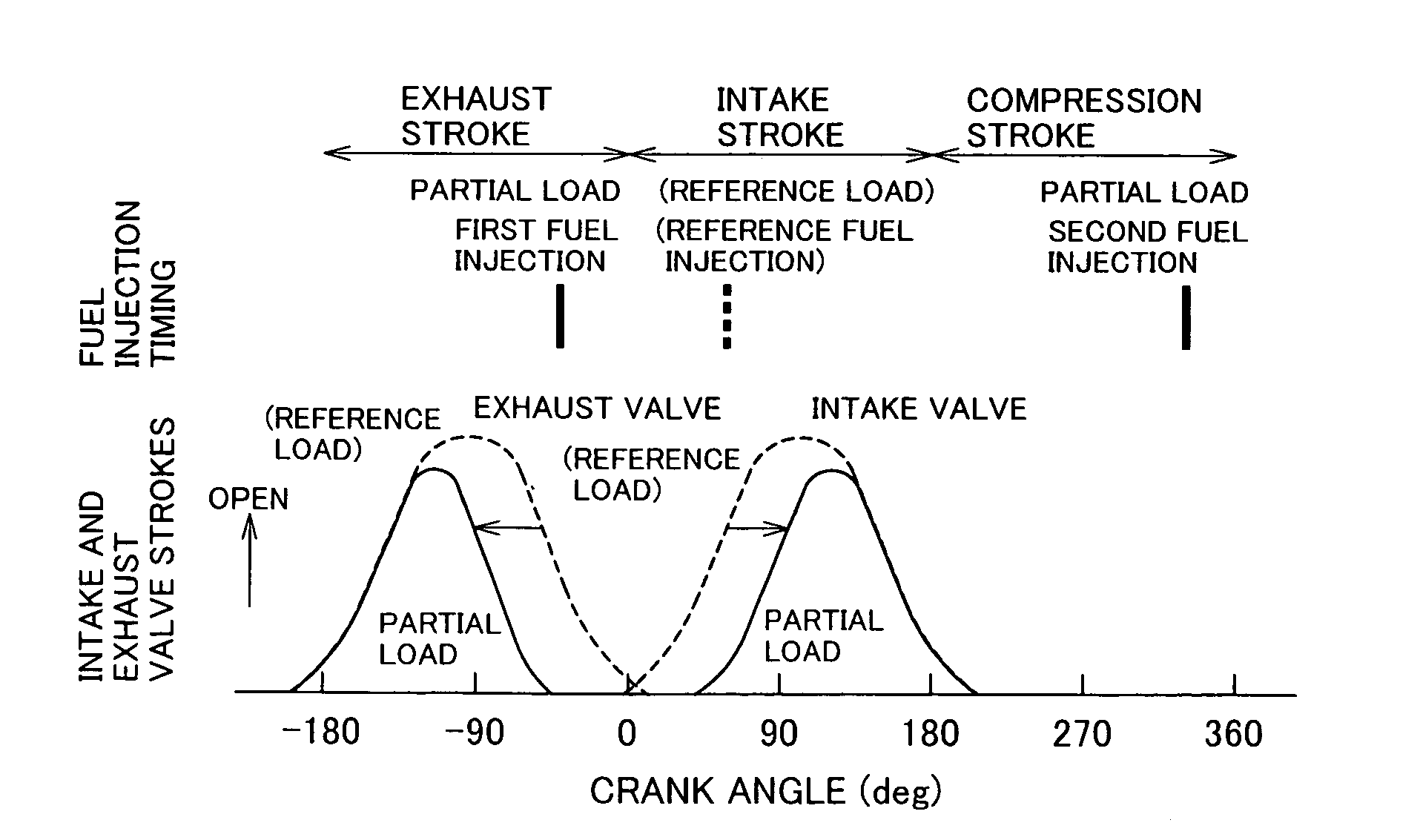
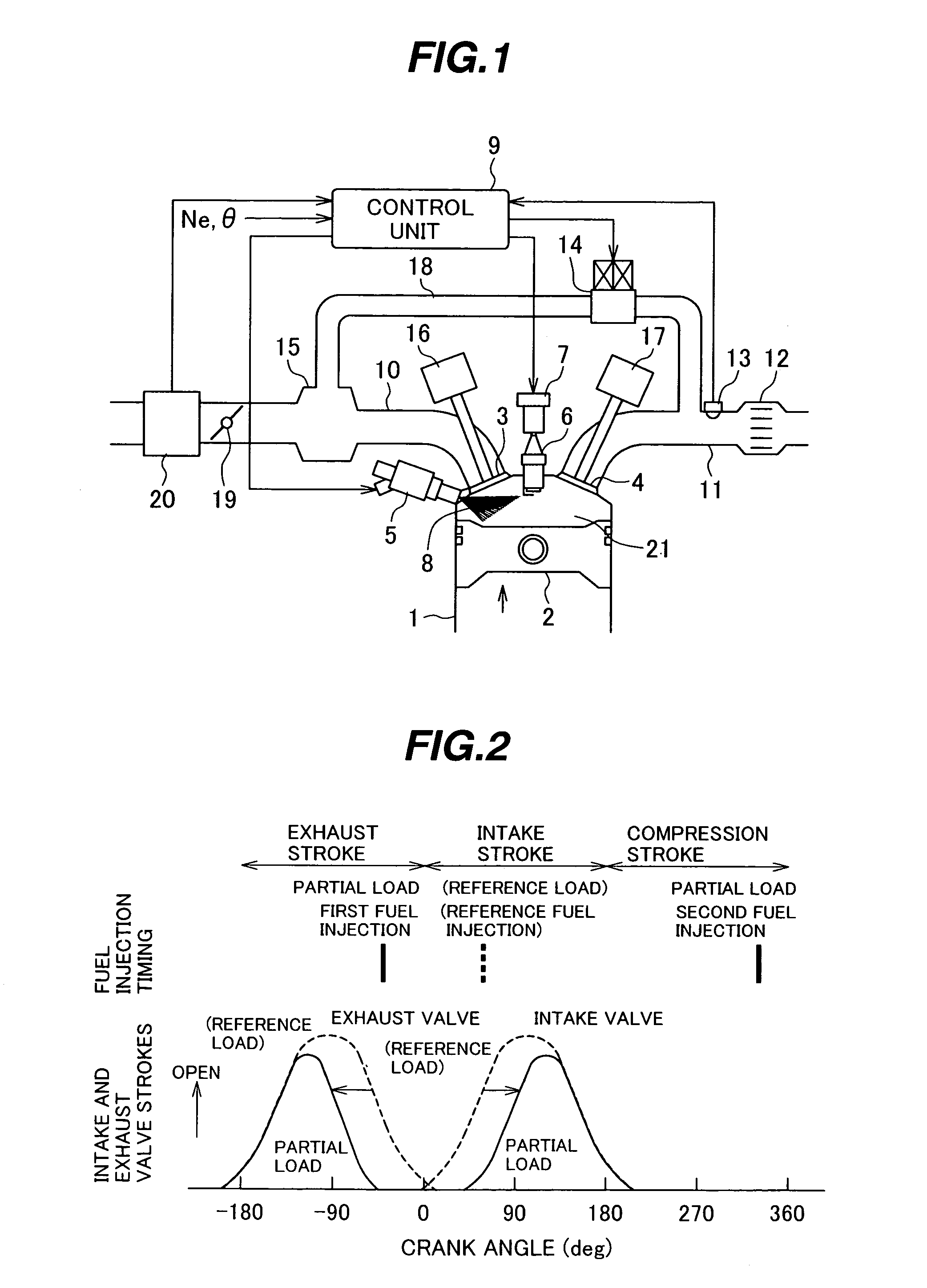
[0050]FIG. 2 shows a valve opening / closing mode (opening and closing timings and lift amount) of each of the intake valve 3 and the exhaust valve 4, and a fuel injection mode (number of injection times and fuel injection timing) provided by the fuel injection valve 5, wherein the engine is operating in the reference load range and the partial load range, and wherein, as described in the aforesaid item (A), as the valve control devices 16 and 17, ones by which the valve opening timing and the valve lift amount of the intake valve 3, and the valve closing timing and the valve lift amount of the exhaust valve 4 are made variable, are employed.

[0051]In FIG. 2, the lateral axis indicates the crank angle that is 0 degree at the top dead center position in the exhaust stroke, and the longitudinal axis indicates the stroke (lift amount) of each of the intake valve 3 and the exhaust valve 4. Here, the valve opening / closing mode and the fuel injection timing under the condition that the engi...

third embodiment

[0070] shown in FIG. 7, when the fuel injection quantity calculated based on operating conditions of the engine 1 is more than three times the minimum controllable quantity of the fuel injection valve 5, the fuel injection is performed by dividing it into three-time injections. When performing injections three times, the first-time, second-time, and third-time injections, respectively, are performed in the latter half of the exhaust stroke, the first half of the intake stroke, and the latter half of the compression stroke. With this arrangement, the effect produced by early closing the exhaust valve 4 to cause exhaust gases to remain (internal EGR) as described above, and the homogenization of air-fuel mixture can be simultaneously achieved. More specifically, in this case, not only the air-fuel mixture in the overall cylinder can be made more uniform, but also the air-fuel mixture in the vicinity of the ignition plug 6 can be made a little richer, and therefore, even though a large...

fourth embodiment

[0072]FIG. 9 shows a valve opening / closing mode (opening and closing timings) of each of the intake valve 3 and the exhaust valve 4, and a fuel injection mode (number of injection times and fuel injection timing) provided by the fuel injection valve 5, wherein the engine is operating in the reference load range and the partial load range, and wherein, as described in the aforesaid item (B), as the valve control devices 16 and 17, the ones (valve timing control mechanisms (VTCs)) by which the opening timing and the closing time of each of the intake valve and the exhaust valve are made simultaneously shiftable, are employed. In this embodiment, under the partial load condition, the opening and closing timings of the exhaust valve 4 are moved toward the advance angle side (i.e., are advanced) by approximately 45 degrees relative to the case under the reference load condition, and simultaneously, the opening and closing timings of the intake valve 3 are moved toward the retard angle s...


PUM


Abstract

A combustion control device and a method for a direct injection engine are disclosed wherein, when the engine is operating in the partial load range, the valve opening/closing mode of an intake valve and/or an exhaust valve is controlled so that exhaust gases remain in a combustion chamber; and control is performed such that fuel is injected from a fuel injection valve into residual exhaust gases at least once during the time period from the latter half of an exhaust stroke to the first half of an intake stroke in one combustion cycle, and that an air-fuel mixture is ignited in the latter half of a compression stroke thereafter.

Description

BACKGROUND OF THE INVENTION[0001]1. Field of the Invention[0002]The present invention relates to a combustion control device and a combustion control method for a spark ignition direct injection engine. More particularly, the present invention pertains to a combustion control device and a combustion control method that promote the vaporization and radicalization of fuel injected from a fuel injection valve into a cylinder taking advantage of the heat of exhaust gases (burned gases), thereby improving the combustibility, fuel economy, exhaust gas purification performance, and the like.[0003]2. Description of the Related Art[0004]The spark ignition direct injection engine injects fuel directly into each cylinder. Accordingly, the spark ignition direct injection engine injects the fuel in the latter half of a compression stroke, and during a stratified charge combustion, in which an air-fuel mixture is burned in the cylinder with the air-fuel ratio distribution of the mixture therein m...

Claims


Application Information

Patent Timeline
IPC IPC(8): F02B3/00F02P5/15F01L1/34F01L13/00F02B17/00F02B23/10F02B75/12F02D13/02F02D41/00F02D41/02F02D41/04F02D41/30F02D41/34F02D41/40F02D43/00F02M25/07
CPCF01L1/34F02D13/0261F02D13/0265F02D41/0002F02D41/3029F02D41/402F02M25/0752F01L13/00Y02T10/42F01L2800/00F02B17/005F02B23/104F02B2075/125F02D41/006F02D41/403F02D2041/001F02D2041/389Y02T10/44Y02T10/18Y02T10/123F02M26/01Y02T10/12Y02T10/40
Inventor FUJIEDA, MAMORUYAMAGUCHI, JUNICHIFUJII, HIROSHIOOSUGA, MINORU
Owner HITACHI ASTEMO LTD
Why Eureka
Try Eureka