Plunger with multiple jackets

Inactive Publication Date: 2006-08-22
GRAY WILLIAM ROBERT
View PDF13 Cites 15 Cited by
  • Summary
  • Abstract
  • Description
  • Claims
  • Application Information

AI Technical Summary

Benefits of technology

[0012]The present invention provides a plunger for use in a gas/fluid lift system in tubulars in wells producing both fluids and gases under variable pressure. The plunger assists with the build up of pressure between the subterranean reservoir and the surface by having an inner seal and an external sliding and variable holding seal with adjacent well tubulars. The inner and external seals restrict the upward flow of the fluids and/or gases. This causes an increase in the well pressure below the plunger and facilitates the upward lifting of the plunger and fluids from the reservoir to the surface when pressure is reduced above the plunger, such as at the well head. The improved plunger comprises a first body and a second body slidingly engageable within the tubulars which is capable of movement up and down the tubulars. Each plunger body has a top end, a bottom end, and an inner core within each body for internal sealing. Each body has at least one separate flexible jacket having a plurality of segments mounted about each core. A connector is disposed between the first and second bodies and joins the bodies. Alternatively

Problems solved by technology

However, because such resilient compounds, like rubber, do not last for extended periods of time in the harsh well environment, problems with inner sealing develop and the plunger must be taken out of service for time-consuming seal replacements.
Further, if the inner spring member which assists in biasing of the segments becomes detached or lost, sealing problems can result.
However, the segments of this design can be prone to leakage.
However, the grooves are prone to structural failure due to external wear and erosion due to contact with the tubulars, and these plungers can also become

Method used


Image

  • Plunger with multiple jackets
  • Plunger with multiple jackets
  • Plunger with multiple jackets

Examples


Example

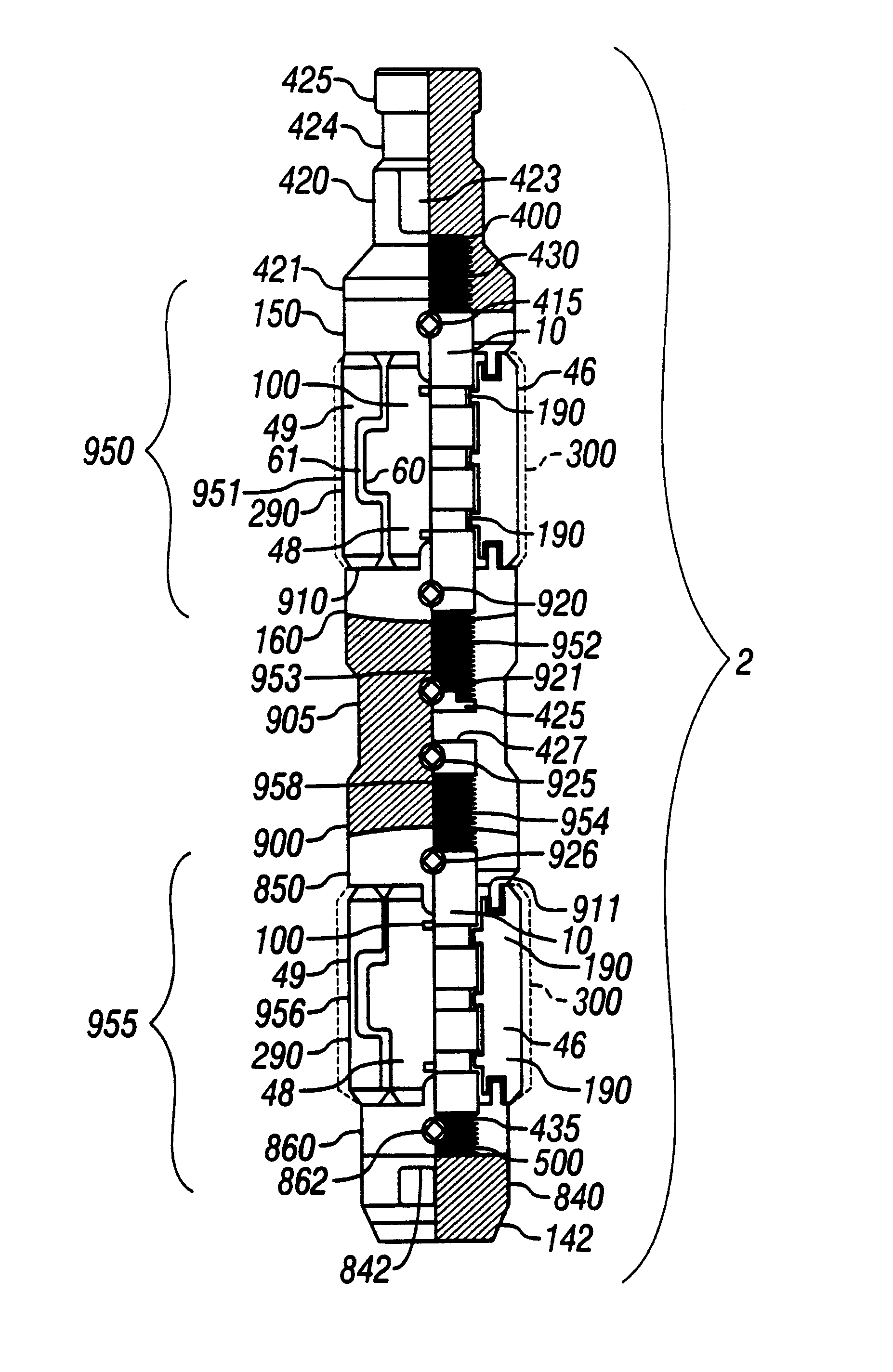
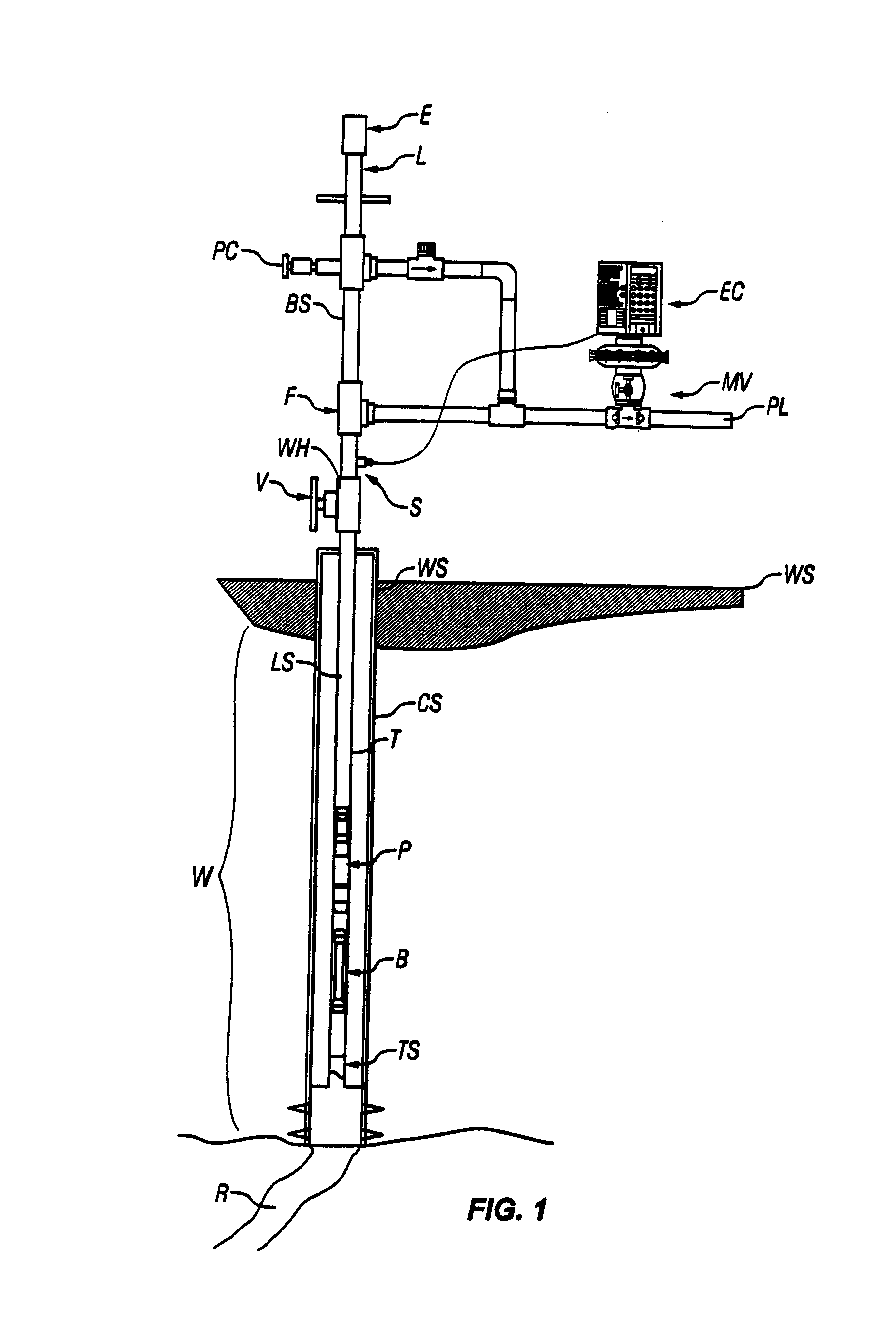
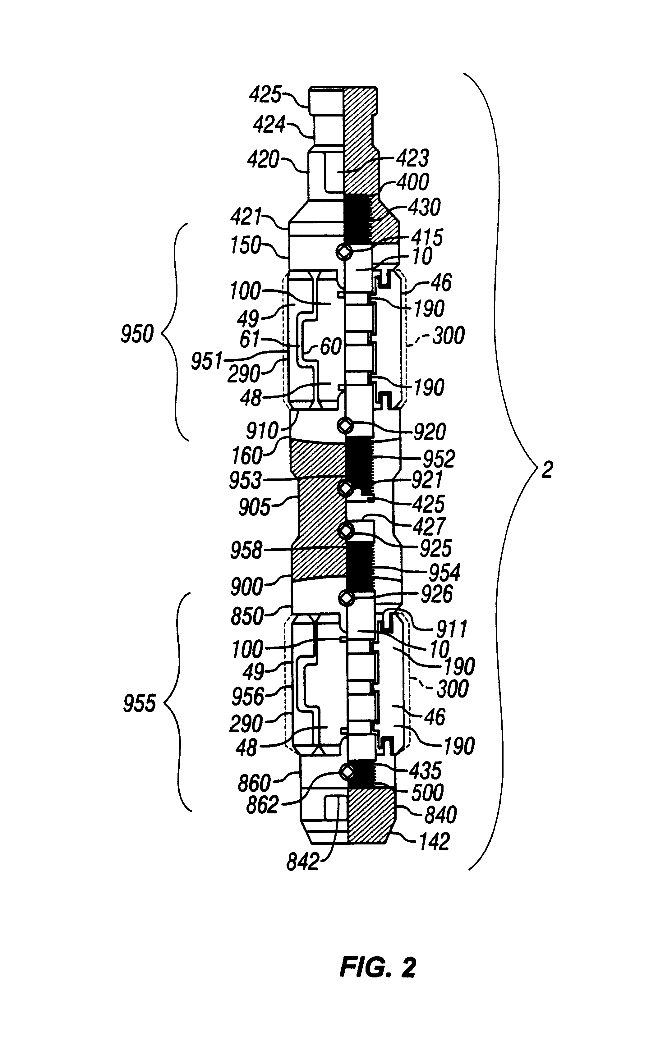
[0045]Referring first to FIG. 1, there is shown a producing well W for producing hydrocarbon fluids from a subterranean reservoir R. The well may be of the horizontal or vertical variety. The plunger pump P is preferably used in wells where the gas pressure alone is insufficient to produce the flow of liquids or the significant flow of fluids at the surface. In these situations, hydrocarbons from such wells cannot be recovered except through the installation of considerably expensive conventional or submersible pump units which require daily inspection and maintenance. Similarly, in wells producing primarily gas, the gas production may be substantially impaired by fluids, whether hydrocarbons or salt water, which accumulate in the bottom of the well. In either event, it is desirable to remove fluids from the bottom of such wells without installing conventional pumping units. Typically, one or more well conduits extend from the subterranean reservoir R to the well surface WS. In the ...


PUM


Abstract

A plunger for use in tubulars in wells which produce fluids and/or gases under variable pressure. The plunger has at least two separate jackets comprised of segments mounted about one body or bodies joined by a connector, which collectively have increased sealing, holding, and lifting capabilities. A inner turbulent or labyrinth-type seal is accomplished by circumferential grooves on the core and/or fingers which project inwardly from the underside of the segments. The plunger body may also have an internal passage to facilitate more rapid descent, and a simplified stopper housed inside a chamber which is actuated when the plunger reaches a well stop or well bottom and which is held in a closed position by the build up of pressure below the plunger. When the pressure inside the tubulars above the plunger is reduced, the plunger and fluids move upwardly to the surface.

Description

BACKGROUND OF THE INVENTION[0001]1. Field of the Invention[0002]The present invention relates to improvements in plungers used in a gas / fluid lift system in wells producing both fluids and gases, such as petroleum and natural gas, under variable pressure to facilitate the lifting of fluids from a subterranean reservoir to the surface through a well conduit or tubulars. Plungers of this type are designed to minimize the downward flow of fluids as well as the upward flow of gases beneath the plunger as the plunger travels upwardly to the surface. More specifically, the gas plunger invention concerns an improved plunger with at least two separate internal and external sealing apparatuses preferably being separate jacket assemblies which collectively have increased sealing, holding, and lifting capabilities in comparison to the single jacket assembly heretofore described. This is accomplished by joining at least plunger bodies together by means such as a double-ended connector, or provi...

Claims


Application Information

Patent Timeline
IPC IPC(8): E21B33/12E21B43/12F04B47/12F04B53/14
CPCE21B43/121F04B53/14F04B47/12
Inventor GRAY, WILLIAM R.HOLT, JAMES H.
Owner GRAY WILLIAM ROBERT
Why Eureka
Try Eureka