Method and apparatus for maskless photolithography

a maskless and photolithography technology, applied in the field of maskless photolithography, can solve the problems of inability to realize the advantages of maskless systems as a result of efficiencies derived from quantities of scale, distortion and uniformity of images, and still arise, so as to achieve efficient pattern creation and easy and quick creation

Inactive Publication Date: 2006-08-22
UNIV OF SOUTH FLORIDA
View PDF13 Cites 34 Cited by
  • Summary
  • Abstract
  • Description
  • Claims
  • Application Information

AI Technical Summary

Benefits of technology

[0028]The subject invention can allow the ability to photoform continuously variable pattern thickness on substrates by using the disclosed gray scale lithographic techniques that do not have a gray scale mask as an element in the gray scale lithographic system. Another advantage of the invention is the ability to efficiently create patterns on larger areas than conventionally possible.
[0029]By providing the ability to individually control the individual micromirrors of the mirror array, any arbitrary micro or macroscopic structure can easily and quickly be created in substrates such as polymers, metals, or ceramics. Patterns such as glasses, microfluidic networks, thin film devices, hybrid material devices, micro electro

Problems solved by technology

While the previously described maskless photolithography systems address several of the problems associated with mask based photolithography systems, such as distortion and uniformity of images, problems still arise.
Notably, in environments requiring rapid prototyping and limited production quantities, the advantages of maskless systems as a result of efficiencies derived from quantities of scale are not realized.
Further, prior art references lack the ability to provide rapid prototyping.
In particular, alignment of patterns with respect to target substrates in maskless systems can be problematic.
In a rapid prototyping, limited quantity environment, automated means of initial alignment are not cost effective.
In addition, conventional maskless alignment systems are normally limited to coplanar, two-dimensional alignment.
In the third dimension, computerized shifting of the mask pattern cannot compensate for misalignments in a direction parallel with an incident light beam.
Another problem with maskless photolithography systems is that the mask pattern image projected is formed by pixels, instead of continuous lines.
As a result, gaps may exist between adjacent pixels, which, when projected on a substrate, may allow the area between the pixels to be exposed, resulting in a break in the imaged pattern.
For example, if the desired pattern is a circuit, gaps may be inadvertently exposed and formed in a trace, resulting in an electrical gap.
The exposure gaps caused by the pixel nature of the micromirror arrays, or pixelation, may cause open circuits or unwanted c

Method used


Image

  • Method and apparatus for maskless photolithography
  • Method and apparatus for maskless photolithography
  • Method and apparatus for maskless photolithography

Examples


Embodiment Construction

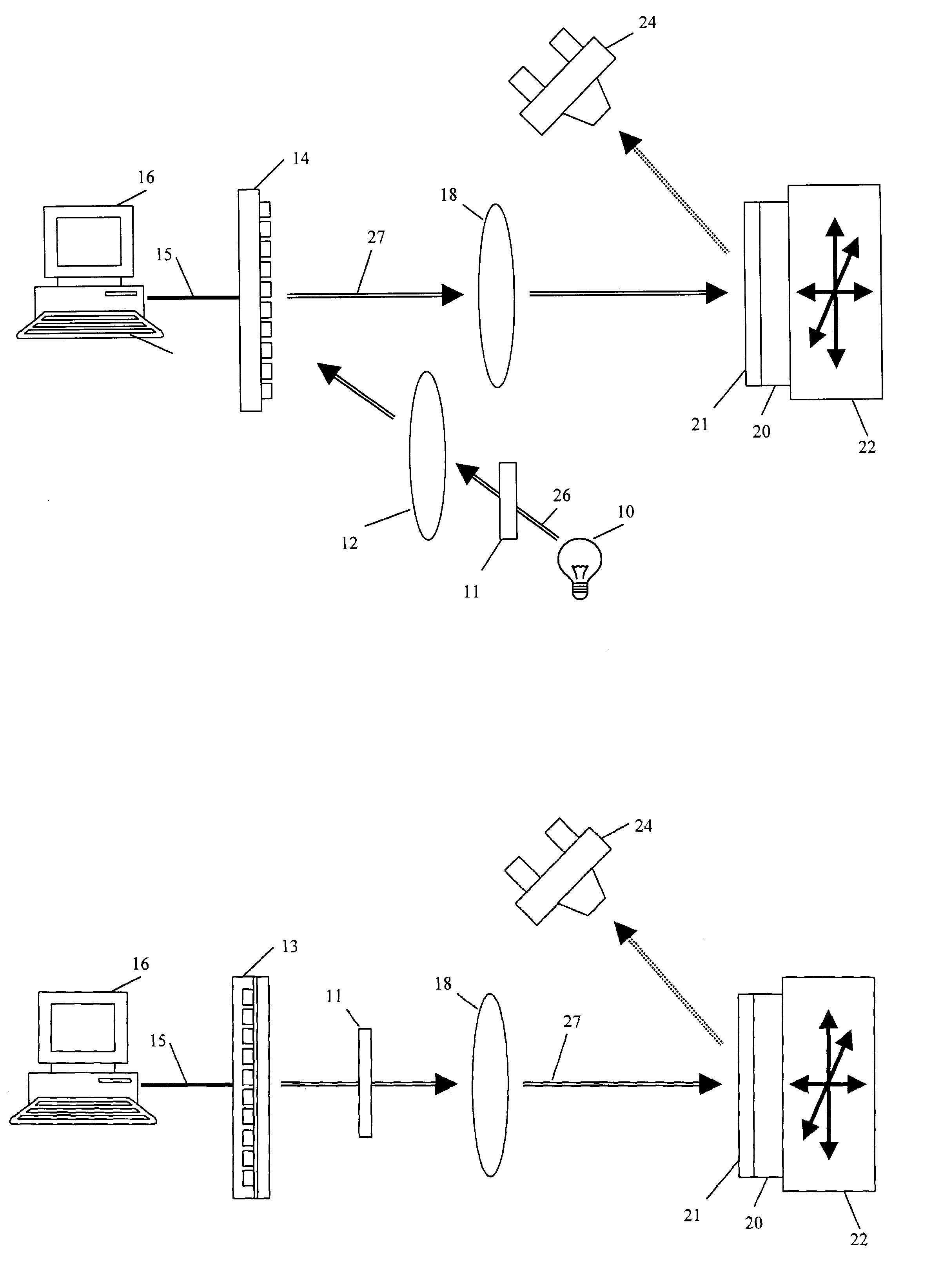
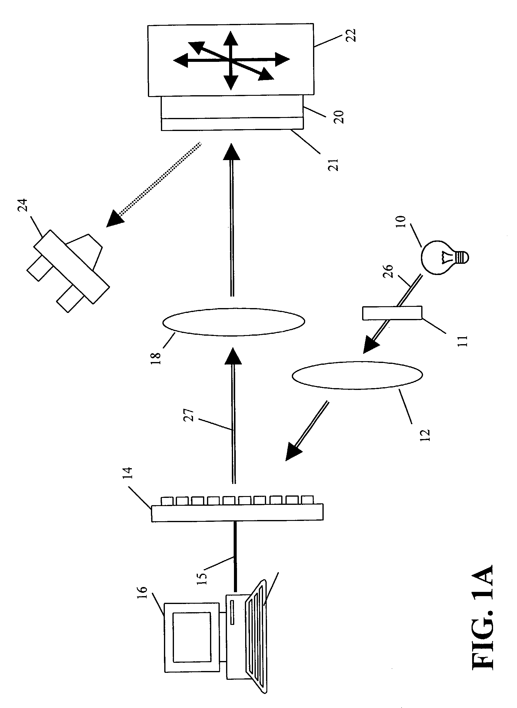
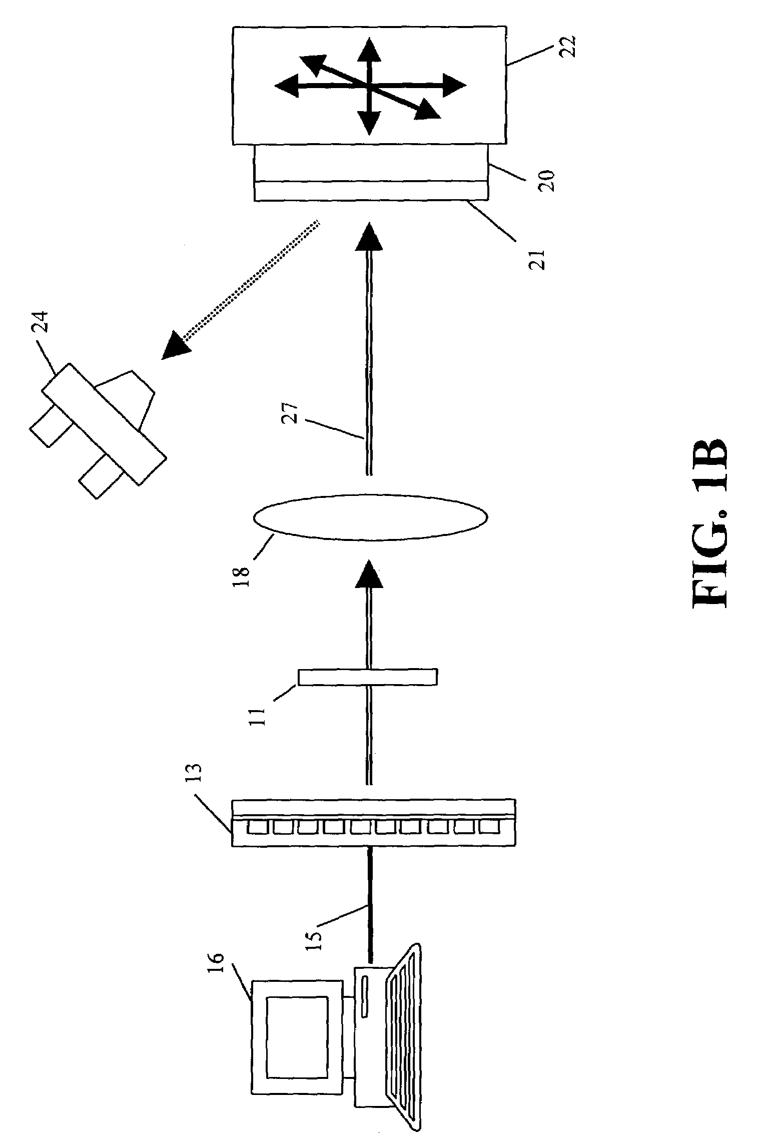
[0043]References will now be made in detail to the embodiments consistent with the invention, examples of which are illustrated in the accompanying drawings. First, briefly, the invention is a system and method to create two dimensional and three dimensional structures using a maskless photolithography system comprising a maskless pattern generator that is directly reconfigurable and does not require masks, templates or stencils to create each of the planes or layers on a multi layer two-dimensional or three dimensional structure. In an embodiment, the invention uses a micromirror array comprising up to several million elements to modulate light onto a substrate that has photoreactive or photoresist compounds applied to the exposed surface. The desired pattern is designed and stored using conventional computer aided drawing techniques and is used to control the positioning of the individual mirrors in the micromirror array to reflect the corresponding desired pattern. Light impingin...


PUM


Abstract

A method and apparatus to create two dimensional and three dimensional structures using a maskless photolithography system that is semi-automated, directly reconfigurable, and does not require masks, templates or stencils to create each of the planes or layers on a multi layer two-dimensional or three dimensional structure. In an embodiment, the pattern generator comprises a micromirror array wherein the positioning of the mirrors in the micromirror array and the time duration of exposure can be modulated to produce gray scale patterns to photoform layers of continuously variable thickness. The desired pattern can be designed and stored using conventional computer aided drawing techniques and can be used to control the positioning of the individual mirrors in the micromirror array to reflect the corresponding desired pattern. A fixture for mounting of the substrate can be incorporated and can allow the substrate to be moved three dimensions. The fixture can be rotated in one, two, or three directions.

Description

CROSS-REFERENCE TO A RELATED APPLICATION[0001]This application is a continuation-in-part of U.S. patent application Ser. No. 10 / 179,083, filed on Jun. 25, 2002, and is a continuation-in-part of U.S. patent application Ser. No. 10 / 179,565, filed on Jun. 25, 2002, both of which claim priority to U.S. Provisional Application Ser. No. 60 / 301,218, filed Jun. 27, 2001, which are incorporated herein by reference.[0002]The subject invention was made with government support under a research project supported by The Office of Naval Research funding reference number N00014-98-1-0848. The government has certain rights in this invention.BACKGROUND ART[0003]Photolithography systems are known in the art that direct light beams onto a photosensitive surface covered by a mask, etching a desired pattern on the substrate corresponding to the void areas of the mask. Maskless photolithography systems are also known in the art as described in Singh-Gasson, Sangeet et al., Nature Biotechnology 17, 974–78,...

Claims


Application Information

Patent Timeline
IPC IPC(8): G03B27/32G03B27/42G03B27/54
CPCG03F7/70291
Inventor FRIES, DAVID P.
Owner UNIV OF SOUTH FLORIDA
Why Eureka
Try Eureka