Air supply system for a motor vehicle

a technology for air supply systems and motor vehicles, which is applied in the direction of braking systems, shock absorbers, brake components, etc., can solve the problems of not being able to supply consumers outside of the closed loop, not being able to fully utilize the power capacity of the compressor, and being very expensive in its manufacture. , to achieve the effect of reducing the manufacturing cost of such an air supply system, reducing the bypass flow, and simplifying the configuration of the pneumatic loop

Inactive Publication Date: 2006-08-29
CONTINENTAL AG
View PDF5 Cites 40 Cited by
  • Summary
  • Abstract
  • Description
  • Claims
  • Application Information

AI Technical Summary

Benefits of technology

[0011]The new air supply system eliminates the above-mentioned disadvantages of the state of the art. Accordingly, only two 3 / 2-directional valves are needed compared to four 2 / 2-directional valves in accordance with the closest state of the art. This simplifies the configuration of the pneumatic loop and thereby reduces the manufacturing cost of such an air supply system. The special advantage of the new air supply system is that, in the phase for filling the vehicle tires, dry and compressed air from the pressurized air supply cannot escape either via the intake line and the running compressor or via the non-used store pressure line and the dryer and cannot mix with the fresh air flow drawn in by suction for filling the tires. The leakage via the compressor is prevented by the pressure position of the 3 / 2-directional valve in the store pressure line and the switchable check valve in the bypass line of the store pressure line prevents the escape of the pressurized air via the dryer. The pressure position of the 3 / 2-directional valve blocks the intake line.
[0012]It is also advantageous that the additional check valve is a 2 / 2-directional valve and is mounted in the bypass line because, in this way, the 2 / 2-directional valve can be configured to be built very small because of the throttled and therefore reduced bypass flow. The additional complexity is, in addition, still reduced in that the additional 2 / 2-directional valve and the bypass throttle are combined in a valve combination.
[0013]It is also advantageous if the line, which extends from the switchable outlet valve of the directional valve unit into the atmosphere, is utilized as a second consumer pressure line for the supply of the external consumer. This saves additional complexities for the realization of the second consumer pressure line.

Problems solved by technology

This embodiment of the air supply system has the disadvantage that no consumer, which lies outside of the closed loop, can be supplied with pressurized air.
In this way, the power capacity of the compressor is not fully utilized.
This embodiment has the disadvantage that it is very complex and therefore very expensive with respect to its manufacture.
This is caused by the additional units for tire filling and has its cause, however, also in the plurality of 2 / 2-directional valves required for the closed loop.

Method used


Image

  • Air supply system for a motor vehicle
  • Air supply system for a motor vehicle

Examples


Embodiment Construction

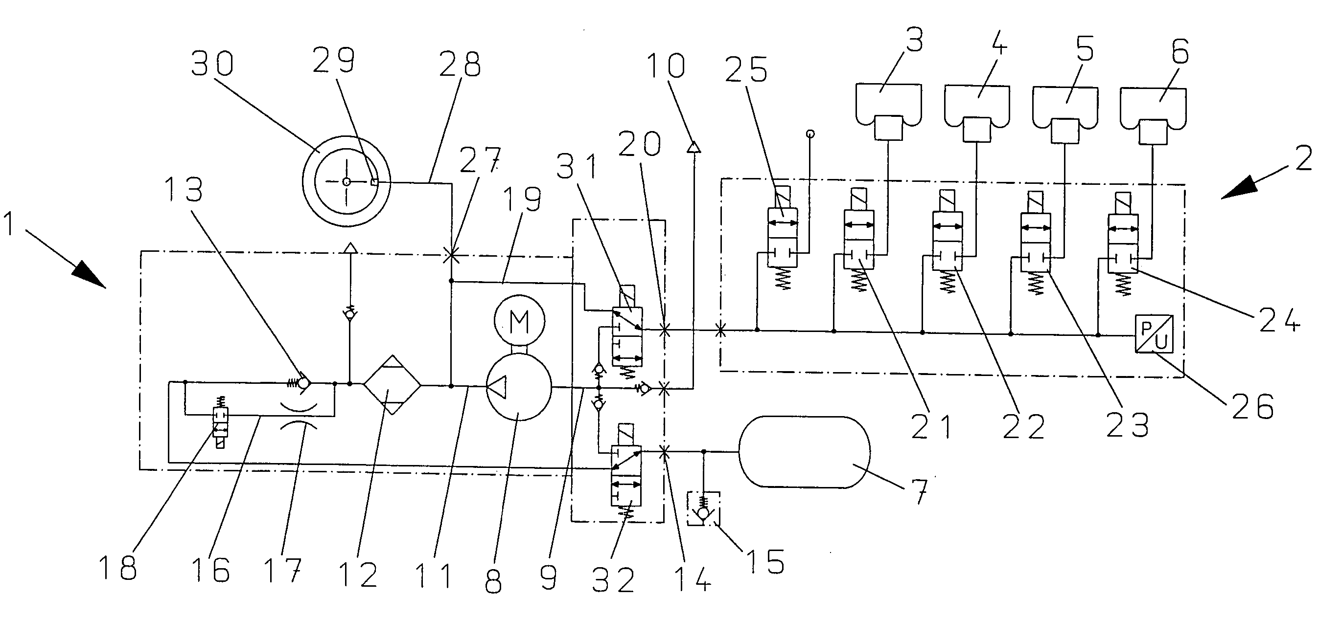
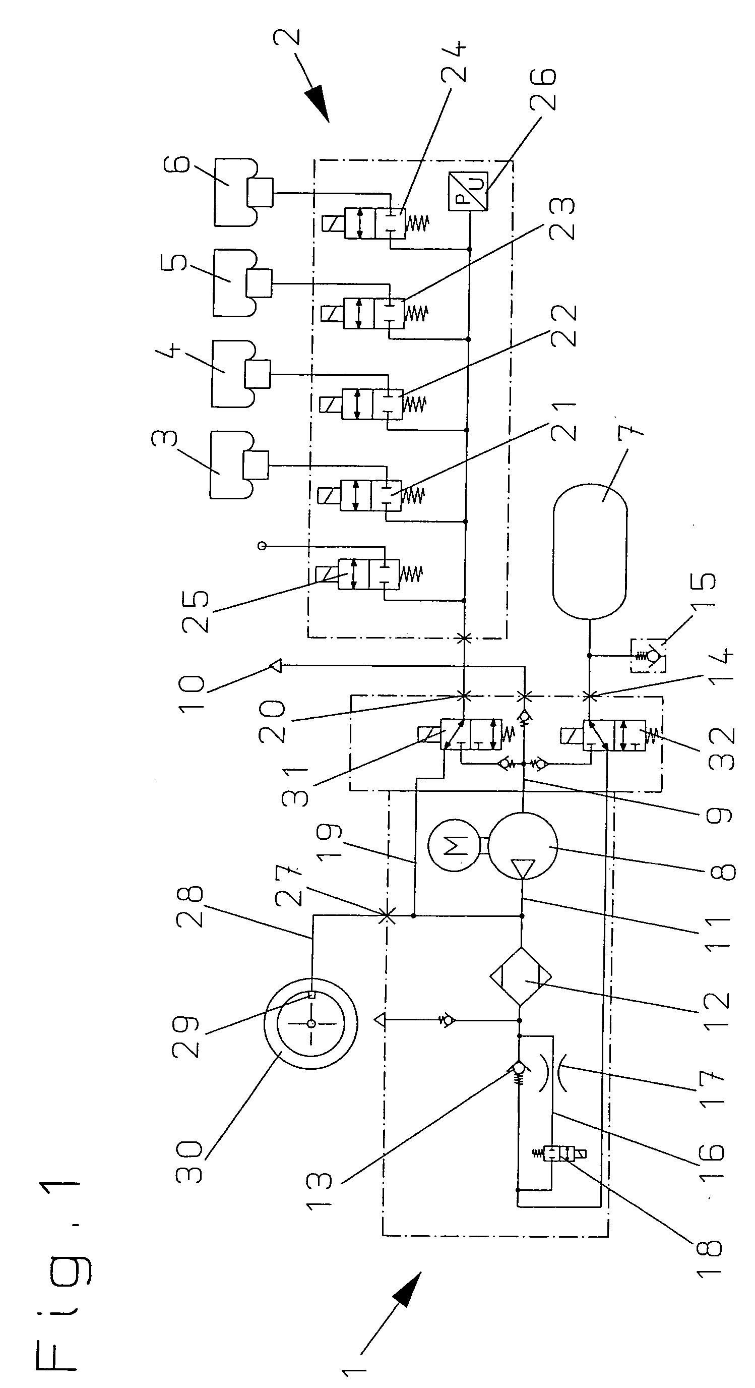
[0015]The air supply system of the invention essentially comprises: a drive unit 1, a directional valve unit 2, four air spring damper units 3 to 6 and a pressurized air store 7.

[0016]The primary component of the drive unit 1 is a compressor 8 which is driven by an electric motor M and which, on the one hand, is connected via an intake line 9 to an intake connection 10 leading into the atmosphere. On the other hand, the compressor 8 has a store pressure line 11 which leads via a dryer 12 and a check valve 13 to a store connection 14. The store connection 14 of the drive unit 1 is connected to the pressurized air store 7 and an intake valve 15, which is connected to the atmosphere, is disposed between the store connection 14 and the pressurized air store 7. The check valve 13 is arranged in the store pressure line 11 so that it opens in the direction toward the pressurized air store 7. In addition, a bypass line 16 is disposed in the store pressure line 11. The bypass line 16 bypasse...


PUM


Abstract

In addition to the consumers of a closed loop, known air supply systems also can supply an external consumer with fresh pressurized air. These systems are very complex with respect to apparatus and furthermore have the disadvantage that already improved pressurized air can escape from the pressurized air store during the supply of the external consumer. A switchable 3/2-directional valve (31) is arranged in the first consumer pressure line (19) of the drive unit (1) and a switchable 3/2-directional valve (32) is mounted in the store pressure line (11) of the drive unit (1) and a switchable check valve is mounted in the bypass line (16) of the store pressure line (11). This check valve disables the throttle function of the bypass throttle (17).

Description

CROSS REFERENCE TO RELATED APPLICATION[0001]This application claims priority of German patent application no. 103 22 578.1, filed May 20, 2003, the entire content of which is incorporated herein by reference.BACKGROUND OF THE INVENTION[0002]Air supply systems are utilized especially for supplying air spring damper units for the leveling control of a motor vehicle within a closed loop but also to supply external consumers.[0003]U.S. Pat. No. 6,726,189 discloses one such air supply system in various embodiments.[0004]In the first embodiment of FIG. 1 of this patent, the air supply system comprises: several air spring damper units arranged in parallel to each other, a compressor and a pressurized air store. A 2 / 2-directional valve is assigned to each air spring damper unit and the air spring damper units are connected via a common ring line to the intake end as well as to the pressure end of the compressor. In this ring line, a switchable intake valve is also provided. A second ring li...

Claims


Application Information

Patent Timeline
Patent Type & Authority Patents(United States)
IPC IPC(8): F16F5/00B60G17/052
CPCB60G17/0523B60G2202/412B60G2206/0116B60G2500/205B60G2500/02B60G2500/2014B60G2500/203B60G2400/51222
Inventor FOLCHERT, UWE
Owner CONTINENTAL AG
Why Eureka
Try Eureka