Hydrodynamic bearing for a spindle motor

a technology of hydrodynamic bearing and spindle motor, which is applied in the direction of sliding contact bearing, record information storage, instruments, etc., can solve the problems of motor failure, ball bearings creating debris, mechanical friction inherent in ball bearings also generating heat, noise and vibration, etc., to reduce the overall power draw of the spindle motor, reduce the overall power loss, and the effect of high degree of effectiveness

Inactive Publication Date: 2006-08-29
MINEBEA CO LTD
View PDF5 Cites 7 Cited by
  • Summary
  • Abstract
  • Description
  • Claims
  • Application Information

AI Technical Summary

Benefits of technology

[0010]It is an object of the present invention to provide a hydrodynamic bearing for a spindle motor, especially for use in a disk dr...

Problems solved by technology

Ball bearings are known to wear parts, and, in time, increased friction will cause failure of the motor.
In addition, ball bearings create debris in the form of dust or fine particles that can find their way into “clean” chambers housing the rotary magnetic disks which are driven by the motor.
The mechanical friction inherent in...

Method used


Image

  • Hydrodynamic bearing for a spindle motor
  • Hydrodynamic bearing for a spindle motor
  • Hydrodynamic bearing for a spindle motor

Examples


Embodiment Construction

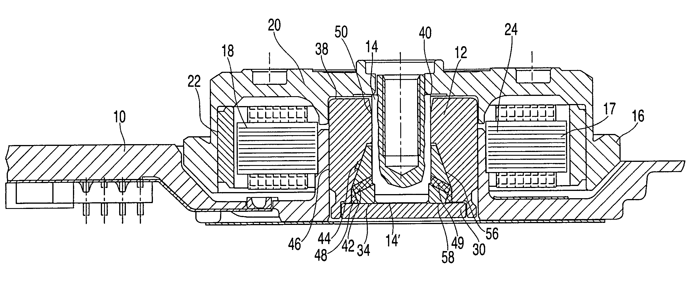
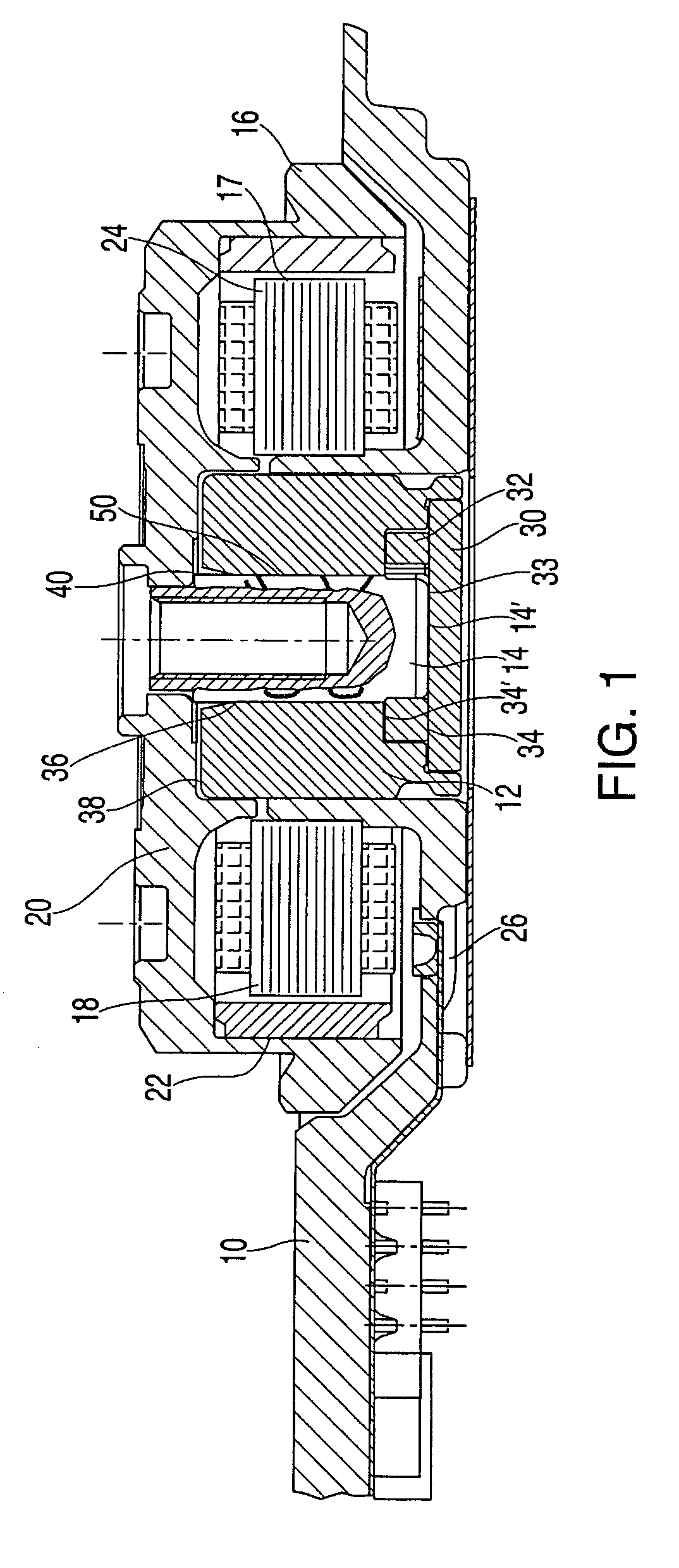
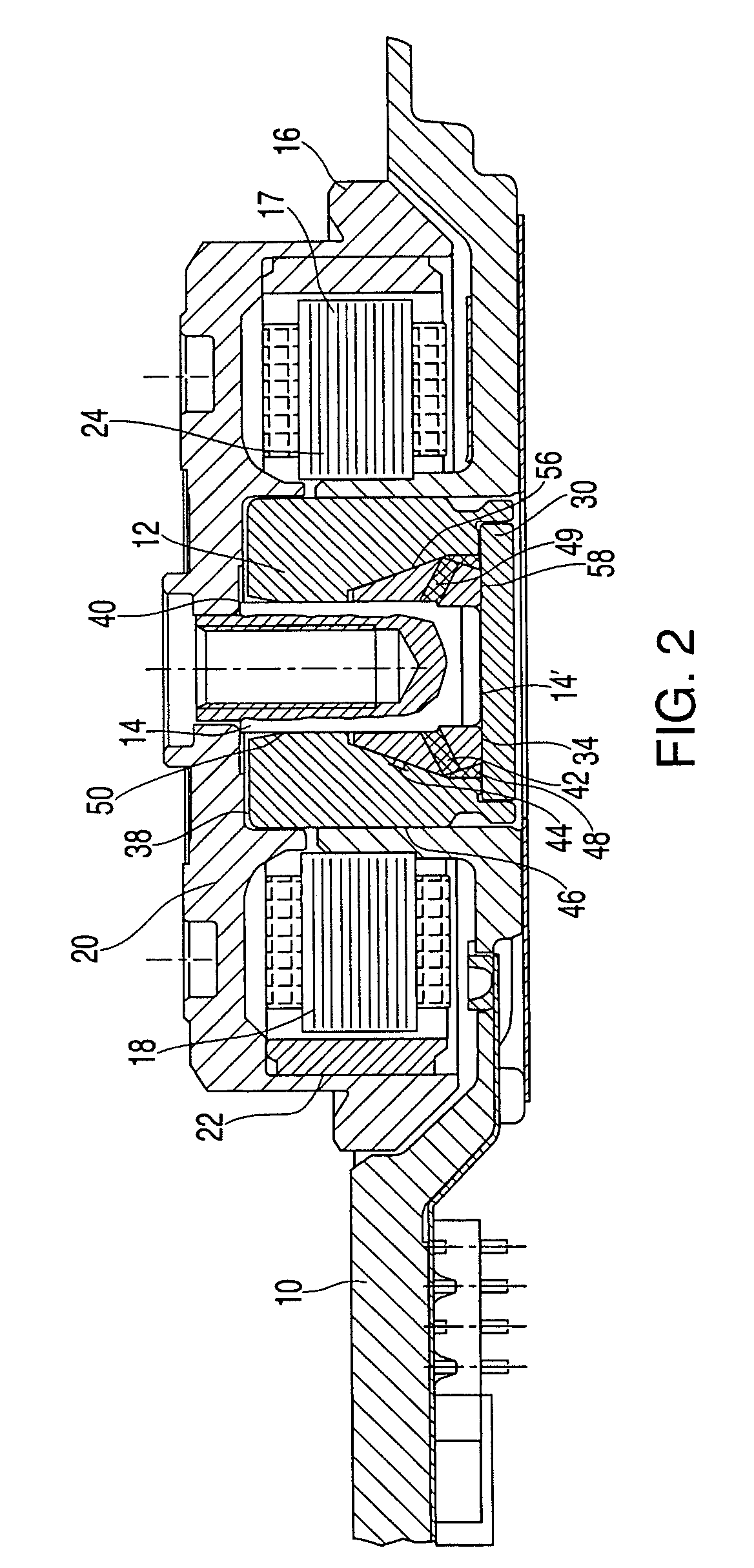
[0027]As shown in FIG. 1, a spindle motor comprises a flange or a base plate 10 to be fastened to a disk drive (not shown). The flange 10 is fixedly secured to a bearing sleeve 12 supporting a shaft 14 for rotation. A rotor 16 is fixedly mounted on the shaft 14, in such a manner as to rotate with the shaft with respect to the flange 10 and the bearing sleeve 12. A stator 18 is fixedly connected to the flange 10.

[0028]The rotor 16 encompasses a hub 20 and the shaft 14, which is coaxially secured to the rotor hub. A rotor magnet 22 is connected to an inner peripheral wall of the rotor hub 20 by, for example, press-fitting or adhesion. The exterior of this peripheral wall of the rotor hub 20 is shaped so that it can support one or more magnetic disks (not depicted).

[0029]The stator 18 comprises a core 24 and stator coil 26 wound around the core 24. The stator 18 and rotor 16 are separated by a thin concentric gap 17, the bearing air gap.

[0030]The bearing sleeve 12 is sealed on one side...


PUM


Abstract

A hydrodynamic bearing for use in a spindle motor, having a shaft, a bearing sleeve encompassing the shaft with a small radial space, and a skewback at one end face of the bearing sleeve which is fixedly connected to the bearing sleeve. The shaft features a thrust plate or a conical or cone-like extension at its end face which faces the skewback. The diameter of the conical extension increases in the direction of the end face of the shaft. A bearing gap formed between the shaft and the bearing sleeve is filled with a bearing fluid. Dynamic pressure generating grooves are provided on one of the outer surface of the shaft and the inner surface of the bearing sleeve to generate an excess pressure in the bearing fluid.

Description

CROSS-REFERENCE TO RELATED APPLICATIONS[0001]This application claims all rights of priority to U.S. Provisional Application Ser. No. 60 / 433,916, filed Dec. 17, 2002 and fully incorporated herein; German Patent Application Serial No. 10256449.3, filed Dec. 3, 2002 (pending) and German Patent Application Serial No. 10305633.5, filed Feb. 11, 2003 (pending).BACKGROUND[0002]The invention relates to a brushless DC motor of the type used in spindle motors in disk drives and, in particular, to a hydrodynamic bearing for such spindle motors.[0003]Disk drive systems have been used in computers and other electronic devices for many years for storage of digital information. Information is recorded on concentric memory tracks of a magnetic disk medium, the actual information being stored in the form of magnetic transitions within the medium. The disks themselves are rotatably mounted on a spindle, the information being accessed by means of transducers located on a pivoting arm which moves radia...

Claims


Application Information

Patent Timeline
IPC IPC(8): F16C17/10F16C33/10G11B19/20H02K7/08
CPCF16C17/026F16C17/10G11B19/2018H02K7/085F16C33/107F16C2370/12
Inventor WINTERHALTER, OLAF
Owner MINEBEA CO LTD
Why Eureka
Try Eureka