Internal combustion engine machine incorporating significant improvements in power, efficiency and emissions control

a technology of internal combustion engine and significant improvement, applied in the direction of machines/engines, mechanical equipment, auxilaries, etc., can solve the problems of reducing the efficiency of both types of engines, and generating excessive fuel and lubricating oil costs, etc., to achieve the effect of improving power, efficiency and emissions control

Inactive Publication Date: 2006-09-12
WARREN III C MADISON
View PDF2 Cites 42 Cited by
  • Summary
  • Abstract
  • Description
  • Claims
  • Application Information

AI Technical Summary

Benefits of technology

[0038]In accordance with preferred embodiments of the invention, there is disclosed a reciprocating internal combustion engine machine incorporating significant improvements in power, efficiency and emissions control, primarily by eliminating the mix lubricating oil with the engine fuel and segregating the lubricating oil and fuel at all times.

Problems solved by technology

Although two-stroke cycle engine technology has many advantages, it has deficiencies have caused widespread legislative restriction on its use and, in the US, an outright EPA ban on it by the year 2006.
Additionally, in nations where sophistication of publicly available technology is low, the prevalent two-cycle technology is producing high levels of air pollution and creating excessive fuel and lubricating oil expense due to the fact that the lubricating oil is burned along with the fuel in inefficient combustion.
However, it is the only technology that the users can afford to acquire and maintain.
No prior technology produced the advantages of both types in one engine.
Prior two-stroke cycle engines suffer a number of deficiencies.
They are inefficient, up to or beyond ten times less efficient than comparable four-stroke cycle engines.
They also inconveniently require that oil be measured and mixed with their fuel.
As a result, prior two-stroke cycle engines operate much less cleanly than comparable four-stroke cycle engines, produce several times the volume of toxic emissions over that of comparable four-stroke cycle engines, experience a high incidence of plug fouling, are notoriously undependable, and use excessive fuel and lubricant.
However, such previous linier designs have had a comparably narrow range of RPM speeds within which they could perform.
These speeds are unsatisfactory for many applications and also complicate engine performance and design parameters for the various internal components.
Prevalent conventional engine technology causes wear on the many moving machine parts, largely due to components of articulated motion.
In present conventional engine technology, high operating temperatures bring increased complexity and expense in engine design and choice of materials.
Present conventional technology is not adaptable to attain significant energy savings by being run on fewer than all cylinders, when full power is not required, letting the unused cylinders and pistons disconnect from the drive train and come to complete rest until again needed.
A number of cam or hydraulically controlled cylinder head exhaust valves are taught in prior two-stroke technology, but none were found teaching cylinder head exhaust valves applied to spark ignited two-stroke technology.
No use of rings on a piston for the purpose of sealing the lubricated space and retaining oil between them has been found in prior technology.
In fact, U.S. Pat. No. 4,364,307 teaches against such usage, particularly noting that it would be inappropriate to place sealing rings both above and below a lubrication groove.
However, none of said patents provide for complete “round trip” oil circulation via this method.
This necessarily limits utility of the oil in cooling the engine, for it must either be slowly metered out so as to prevent a significant amount of it burning with the normal engine combustion, or it must be restricted from the cylinder interior entirely.
(These sealed walls are also known as “cross heads.”) However, as in those described above, none provide for complete oil circulation cycles to include oil return from the engine cylinder to the sump.

Method used


Image

  • Internal combustion engine machine incorporating significant improvements in power, efficiency and emissions control
  • Internal combustion engine machine incorporating significant improvements in power, efficiency and emissions control
  • Internal combustion engine machine incorporating significant improvements in power, efficiency and emissions control

Examples


Embodiment Construction

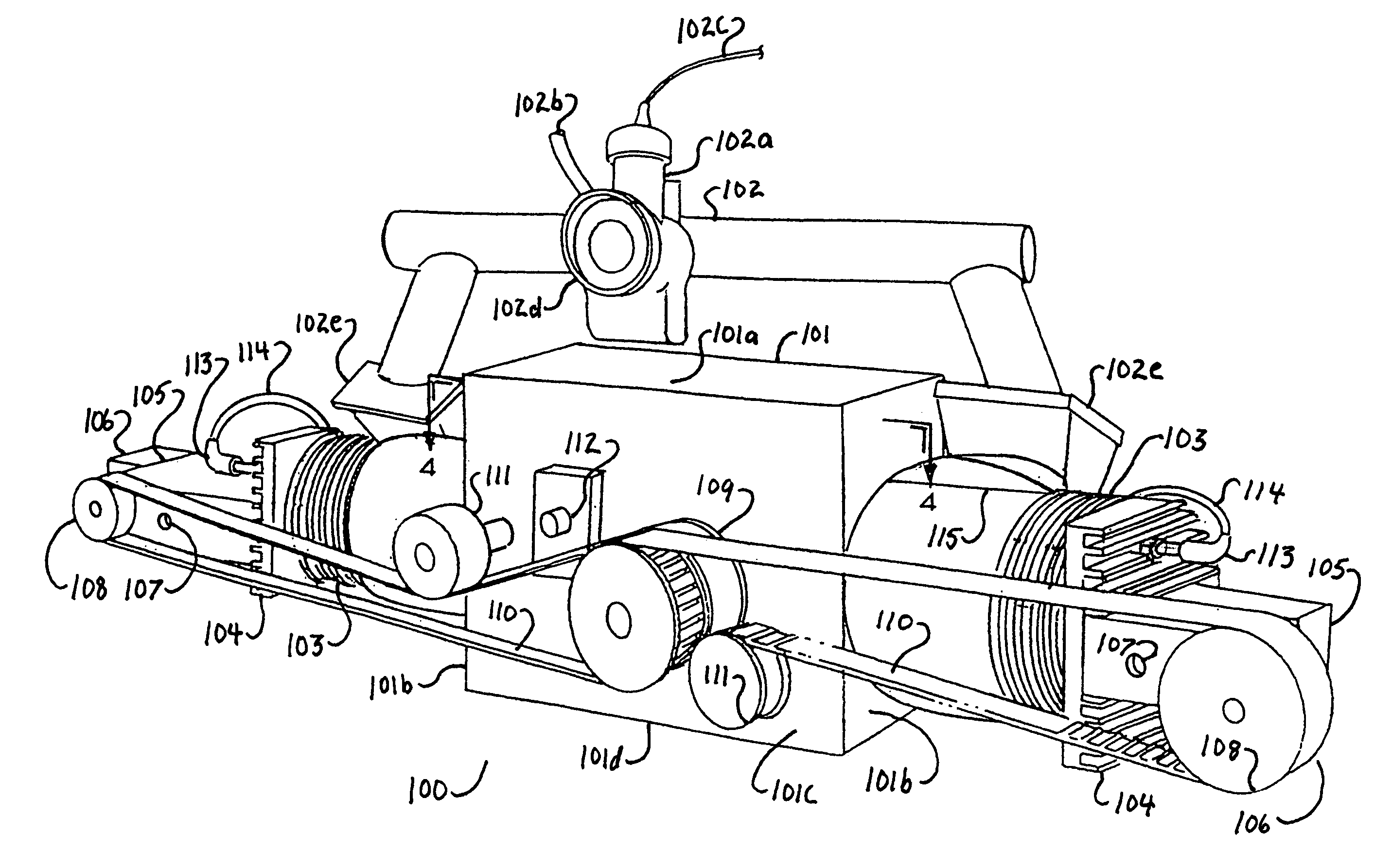
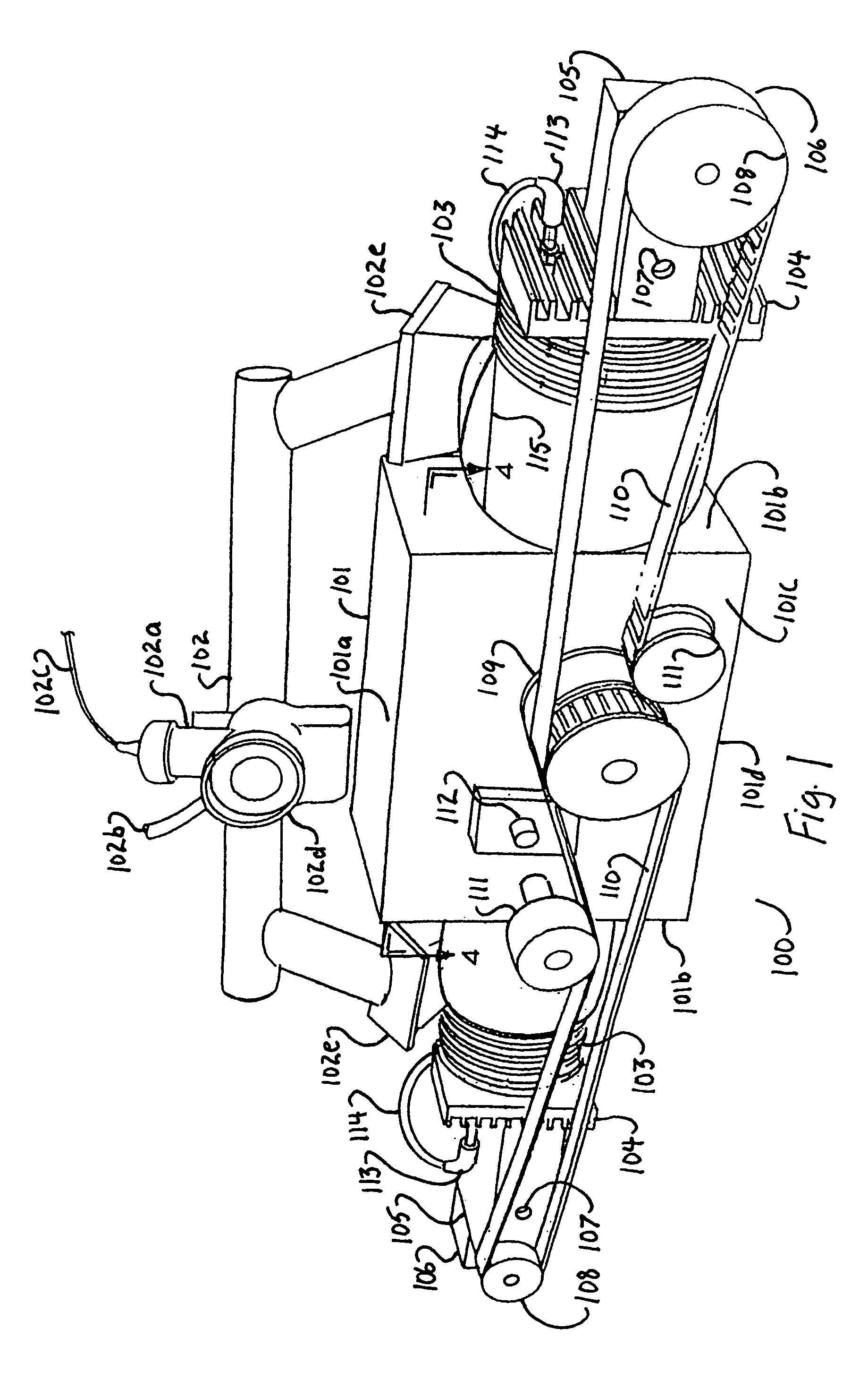
[0241]The key novelties of this invention lie in its means of lubrication combined with its means of aspiration and exhaust. A number of alternative modes are offered and they can be “mixed and matched” as needs dictate. Note that in every mode described, fuel injection may be substituted for carburetion, providing increased performance, but at the expense of increased system complexity and monetary cost.

[0242]Referring to FIG. 1, the engine in the first preferred mode, a two-stroke cycle dynamic pressure powered lubrication configuration (100), has a combination oil sump / crankcase (101) with a top and top plate (101a) and combination end walls / cylinder compression walls (101b), side-walls (101c) and a bottom (101d). It includes an air / fuel intake manifold (102), a carburetor (102a), a fuel inlet (102b), a throttle cable (102c), a carburetor air intake (102d) and a one-way air intake reed valve (102e).

[0243]On either end of the combination oil sump / crankcase is a cylinder (103) with...


PUM


Abstract

A two stroke cycle internal combustion engine machine that does not require lubricating oil to be mixed with its fuel, producing greater efficiency, higher power to weight ratio, cooler operating temperatures, a wider speed range, greater simplicity, and lower toxic emissions, many of the improvements also transferable to four stroke engines.

Description

CROSS REFERENCE TO RELATED APPLICATIONS[0001]This application is based on provisional application Ser. No. 60 / 424,981, filed on Nov. 8, 2002.STATEMENT REGARDING FEDERALLY SPONSORED RESEARCH OR DEVELOPMENT[0002]Not ApplicableDESCRIPTION OF ATTACHED APPENDIX[0003]Not ApplicableBACKGROUND OF THE INVENTION[0004]This invention relates generally to the field of internal combustion engines and more specifically to an internal combustion engine machine incorporating significant improvements in power, efficiency and emissions control.[0005]This invention was conceived in response to the need for greater simplicity, efficiency and power in internal combustion piston engine designs.[0006]Although two-stroke cycle engine technology has many advantages, it has deficiencies have caused widespread legislative restriction on its use and, in the US, an outright EPA ban on it by the year 2006.[0007]Additionally, in nations where sophistication of publicly available technology is low, the prevalent tw...

Claims


Application Information

Patent Timeline
Patent Type & Authority Patents(United States)
IPC IPC(8): F02B75/22F01L1/38F02B75/00F02B75/02F02B75/24F02B75/32
CPCF01B9/026F01L1/38F01L1/40F01L11/02F02B75/005F02B75/02F02B75/24F02B75/32F01M1/06F01L1/024F01L1/34F02B2075/025F01M2001/066
Inventor ROBERTS, FREDDIE RAY
Owner WARREN III C MADISON
Why Eureka
Try Eureka