Non-overlapping antenna pattern diversity in wireless network environments

a wireless network and antenna pattern technology, applied in antennas, electrical equipment, radio transmission, etc., can solve the problems of weak resultant signal (destructive interference), weak resultant signal (constructive interference), and interference at the receiver that must be addressed

Inactive Publication Date: 2006-09-12
CISCO TECH INC
View PDF8 Cites 22 Cited by
  • Summary
  • Abstract
  • Description
  • Claims
  • Application Information

AI Technical Summary

Problems solved by technology

When the coherence bandwidth of the RF channel is on the same order as the signal bandwidth of the signal, multipath in a radio system using most narrow-band or spread spectrum communication techniques results in interference at the receiver that must be addressed.
This interference is a result of the radio receiver performing a vector addition of all the signals received from all of the various paths they follow between the transmitter and receiver.
This vector addition can result in a very weak resultant signal (destructive interference) or a strong resultant signal (constructive interference).
Therefore, spatial diversity has diminished utility with this type of radio signal.

Method used


Image

  • Non-overlapping antenna pattern diversity in wireless network environments
  • Non-overlapping antenna pattern diversity in wireless network environments
  • Non-overlapping antenna pattern diversity in wireless network environments

Examples


Embodiment Construction

)

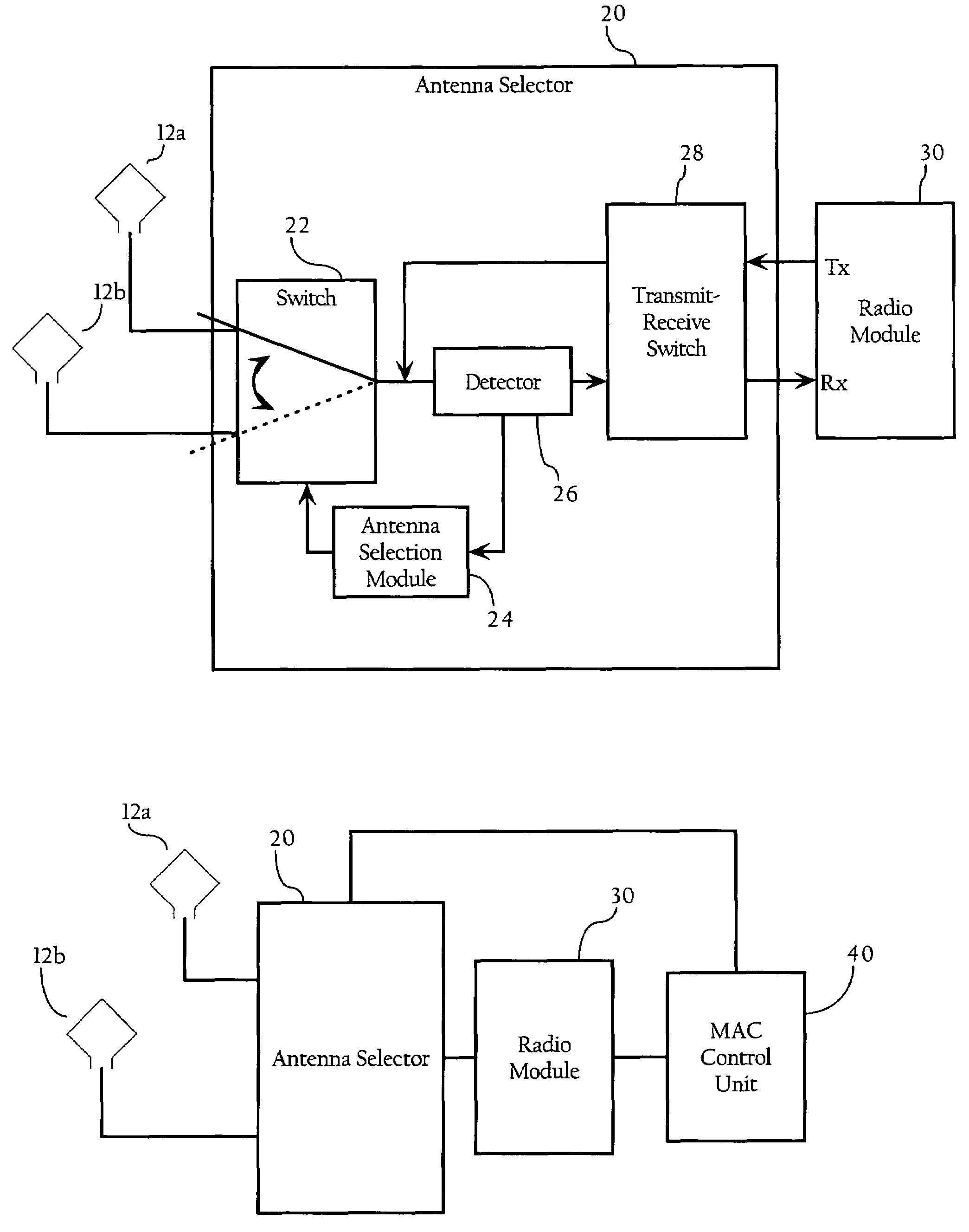
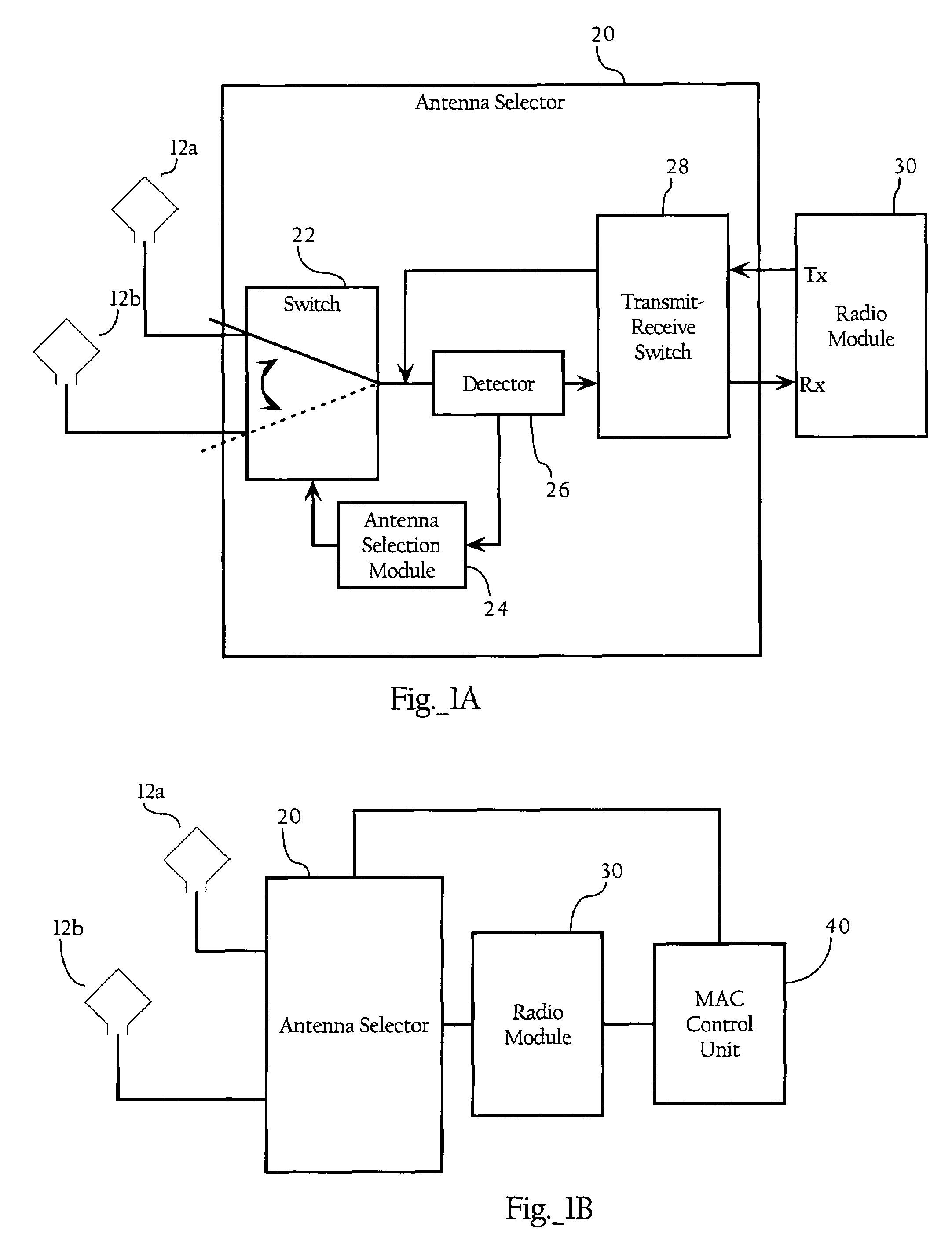
[0019]FIG. 1A illustrates an antenna selector 20, according to an embodiment of the present invention. As FIG. 1B illustrates, the transmit receive unit 20, in one embodiment, is part of a wireless network interface unit 60 comprising antennas 12a, 12b, antenna selector 20, radio module 30, and MAC control unit 40. In one embodiment, the functionality described herein can be implemented in a wireless network interface chip set, such as an 802.11 network interface chip set. Radio module 30 includes frequency-based modulation / demodulation functionality for, in the receive direction, demodulating radio frequency signals and providing digital data streams, and in the transmit direction, receiving digital data streams and providing frequency modulated signals corresponding to the digital data stream. In one embodiment, radio module 30 is an Orthogonal Frequency Division Multiplexed modulation / demodulation unit. In one embodiment, radio module 30 implements the OFDM functionality in a ma...


PUM


Abstract

Methods, apparatuses and systems directed to a wireless network interface supporting directional antenna diversity. Directional diversity, in one embodiment, makes use of antennas with higher gain and non-overlapping patterns to provide communication over a greater area and select the best antenna to receive signals transmitting wireless frames or packets. Certain embodiments optimize wireless network systems using Orthogonal Frequency Division Multiplexed (OFDM) signals where spatial diversity protection provided by spatially-separated, omni-directional antennas is not required. In other embodiments, use and selection of directional antennas allows for sectorization resulting in performance gains such as extended coverage areas, noise reduction, enhanced efficiency, and increased throughput.

Description

CROSS-REFERENCE TO RELATED APPLICATIONS[0001]This application makes reference to the following commonly owned U.S. patent applications and patents, which are incorporated herein by reference in their entirety for all purposes:[0002]U.S. patent application Ser. No. 10 / 155,938 in the name of Patrice R. Calhoun, Robert B. O'Hara, Jr. and Robert J. Friday, entitled “Method and System for Hierarchical Processing of Protocol Information in a Wireless LAN;” and[0003]U.S. patent application Ser. No. 10 / 407,357 in the name of Patrice R. Calhoun, Robert B. O'Hara, Jr. and Robert J. Friday, entitled “Method and System for Hierarchical Processing of Protocol Information in a Wireless LAN.”FIELD OF THE INVENTION[0004]The present invention relates to wireless signals and, more particularly, to methods, apparatuses and systems directed to non-overlapping antenna pattern diversity in wireless network environments.BACKGROUND OF THE INVENTION[0005]A wireless Local Area Network is a wireless communica...

Claims


Application Information

Patent Timeline
Patent Type & Authority Patents(United States)
IPC IPC(8): H01Q21/00
CPCH01Q3/2605H01Q25/00H01Q21/28
Inventor FRIDAY, ROBERT J.
Owner CISCO TECH INC
Why Eureka
Try Eureka