Magneto-optical sensing employing phase-shifted transmission bragg gratings

a transmission bragg grating and phase-shifted technology, applied in the field of fiberoptic sensing applications, can solve the problems of limiting the sensitivity of such sensors, requiring precise surface machining and optical alignment, and small faraday activity of standard optical glass, and achieves excellent electrical isolation, low electronic emission, and light weight

Inactive Publication Date: 2006-09-12
KYTON
View PDF12 Cites 6 Cited by
  • Summary
  • Abstract
  • Description
  • Claims
  • Application Information

AI Technical Summary

Problems solved by technology

One drawback of such optical fiber sensors is the very small Faraday activity of standard optical glass.
Many turns of fiber around the conductor wire or flux path helps to increase the fiber-to-magnetic field interaction length, although birefringence also accumulates per unit length and limits the sensitivity of such sensors.
However, such sensors generally require precise surface machining and optical alignment.
See e.g., N. E. Fisher & D. A. Jackson, Meas. Sci. Technol. 7 (1996)p 1099–1102, but mechanical and environmental stability, complicated installation and higher cost make them impractical.
Such sensors generally exhibit high sensitivity and accuracy, but they can have limited dynamic range due to saturation of magnetic garnets and are also assembled optical components that can become misaligned or damaged with rough use.
Another disadvantage is the relatively high temperature dependence of Faraday rotation in magnetic garnets.
The peculiar geometry of this detector limits its usefulness to detection of current flowing through a wire or to a narrow range of very similar uses.
Another disadvantage was the necessity of breaking the power line during installation and the sensitivity of the sensor to mechanical noise because of the precise fiber-to-bulk glass alignment needed.

Method used


Image

  • Magneto-optical sensing employing phase-shifted transmission bragg gratings
  • Magneto-optical sensing employing phase-shifted transmission bragg gratings
  • Magneto-optical sensing employing phase-shifted transmission bragg gratings

Examples


Embodiment Construction

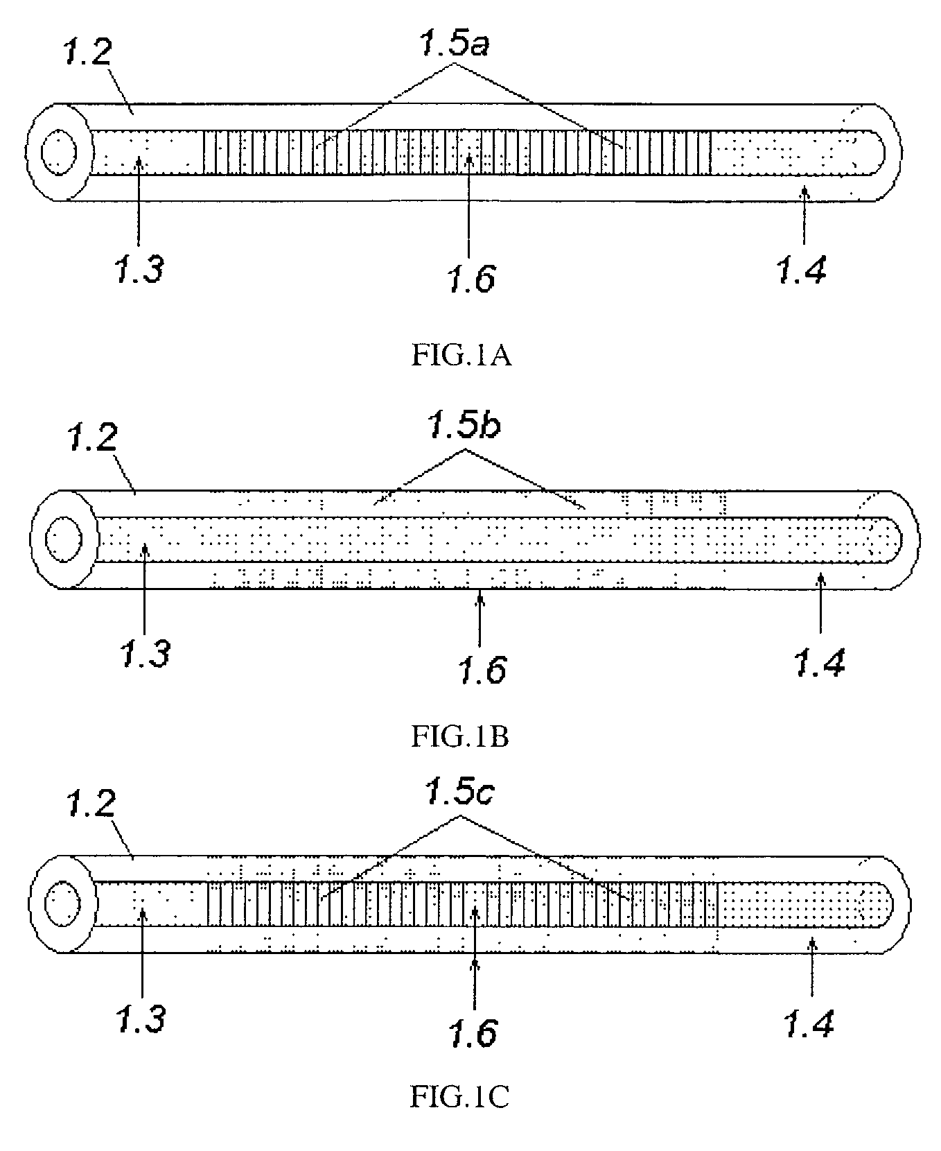
[0062]FIG. 1 shows an exemplary illustrative magneto-optic sensing element in accordance with a non-limiting aspect of a preferred embodiment of the present invention. Referring now to FIG. 1, a magneto-optic sensing element 1.1 is provided by the fiber 1.2 having core 1.3 and cladding 1.4 and having Bragg grating 1.5 written into core 1.5a, cladding 1.5b or both 1.5c by UV laser exposure through a phase mask or any technique well known to those of ordinary skill in the art. The exposed areas of fiber core, cladding, or core and cladding (depending on type of fiber and exposure method) exhibit small changes in refractive index. Although usually the change in refractive index is quite small, the number of such regions can be huge (10000 or more), so the reflectivity level can be very high (up to 0.99999), leading to the possibility of forming high quality FP (Fabry-Perot) resonators. FP resonators will be formed if a Bragg grating 1.5 has at least one phase shift 1.6, equal to intege...


PUM

PropertyMeasurementUnit
interaction lengthaaaaaaaaaa
lengthaaaaaaaaaa

Abstract

A new fiber-optic magnetic field or current sensor design can increase the accuracy, resolution and environmental stability of the subject sensor. The design is based on phase-shifted fiber or planar waveguide Bragg grating, in which a Fabry-Perot resonator is formed around the phase shift. When the wavelength of incident light coincides with the wavelength of FP resonator mode, the magnetic field induced polarization rotation of the waveguided light will be strongly enhanced.

Description

CROSS-REFERENCES TO RELATED APPLICATIONS[0001]This application claims the benefit of priority from application Ser. No. 60 / 338,685 filed Dec. 11, 2001, incorporated herein by reference.STATEMENT REGARDING FEDERALLY SPONSORED RESEARCH OR DEVELOPMENT[0002]Not applicable.FIELD OF THE INVENTION[0003]The invention is related to fiber-optic sensing applications for magnetic fields, including magnetic fields due to electrical currents. More particularly, the invention relates to a phase-shifted fiber or waveguide Bragg grating in which a Fabry-Perot resonator is formed around the phase shift.BACKGROUND AND SUMMARY OF THE INVENTION[0004]Magnetic field and electrical current sensors play an important role in both military and civilian applications. Fiber optic based sensors offer many necessary and attractive benefits that have been driving their development for several decades. These benefits include immunity to electromagnetic interference (EMI), excellent electrical isolation, compatibili...

Claims


Application Information

Patent Timeline
Patent Type & Authority Patents(United States)
IPC IPC(8): G02B6/00G02B6/34G01N21/17G01R15/24G01R33/032G02B6/02G02B6/124G02B6/42H01S5/14H01S5/183
CPCG01N21/1717G01R15/246G01R33/0322G02B6/124G02B6/02109G01N2021/1727H01S5/18366G02B6/4202G02B6/4246
Inventor KOCHERGIN, VLADIMIRSWINEHART, PHILIP
Owner KYTON
Why Eureka
Try Eureka