High-speed PWM control apparatus for power converters with adaptive voltage position and its driving signal generating method

a technology of pwm control and voltage position, which is applied in the direction of dc-dc conversion, power conversion systems, instruments, etc., can solve the problems of low ripple and high accuracy application, method does not work well, and the switching signal cannot respond to the change of loading instantaneously, so as to prevent the overshoot of loading and reduce the cost of components.

Inactive Publication Date: 2006-09-19
NIKO SEMICON +1
View PDF4 Cites 47 Cited by
  • Summary
  • Abstract
  • Description
  • Claims
  • Application Information

AI Technical Summary

Benefits of technology

[0016]One particular aspect of the present invention is to provide a high-speed PWM control apparatus for power converter with adaptive voltage position and its driving signal generation method. The present invention automatically detects the change of the loading and adjusts the voltage position simultaneously for stabilizing the voltage. When the circuit recovers from a heavy loading to a light loading, the present invention prevents the over-shoot of the loading from being produced. Therefore, the circuit components, such as output capacitor, the inductor and the power transistor etc., can be reduced. Therefore, the cost of the component is reduced.
[0017]The present invention does not require the frequency of clock signal to generate a driving signal and does not require an error amplifier to control the modulation. Therefore, the present invention has a fast transient response that responds to the change of the loading instantaneously and stably. When the apparatus is in continuous conduction mode (CCM), the switching frequency of the controller is still fixed even though the input voltage Vin and the output voltage Vout are changed. The electrical-magnetic noise disturbance is therefore improved.
[0019]The compensation unit is used for obtaining a current detection signal and automatically outputs a feedback voltage-adjusting signal according to the current detection signal. The error signal comparison unit is connected with the compensation unit for comparing the feedback voltage-adjusting signal with a reference signal to output a modulation output signal. The logic control unit is connected with the error signal comparison unit for receiving the modulation output signal and outputting a PWM setting signal. The on-time delay control unit is connected with the logic control unit, the input voltage Vin and the reference voltage Vref for generating a PWM reset signal according to the PWM setting signal, the input voltage Vin and the reference voltage Vref. The flip-flop is connected with the logic control unit and the on-time delay control unit for outputting a PWM driving signal according to the PWM setting signal and the PWM reset signal. The PWM driving signal outputs a pair of complementary driving signals DrvH and DrvL via the driving unit. The off-time delay control unit is connected with the flip-flop and the logic control unit for generating a PWM off-time signal according to the PWM driving signal and transmitting the PWM off-time signal to the logic control unit. When the zero current detection unit detects the current flowing through the inductor is zero, the zero current detection unit outputs a zero current enable signal to the driving unit for cutting off the driving signal DrvL of the driving unit. Therefore, an unstable condition of output voltage drop that is produced by a reverse current flowing through the transistor is avoided. Thereby, when the loading is changed, the PWM control apparatus generates the PWM setting signal instantaneously to response rapidly the change of the loading. The power supply is therefore stabilized.

Problems solved by technology

Hence the switching signal cannot respond to the change of the loading instantaneously if the loading changes rapidly.
When the level of the ripples is small, the disturbance of the noise is serious and the method does not work well in low ripple and high-accuracy application.

Method used


Image

  • High-speed PWM control apparatus for power converters with adaptive voltage position and its driving signal generating method
  • High-speed PWM control apparatus for power converters with adaptive voltage position and its driving signal generating method
  • High-speed PWM control apparatus for power converters with adaptive voltage position and its driving signal generating method

Examples


Embodiment Construction

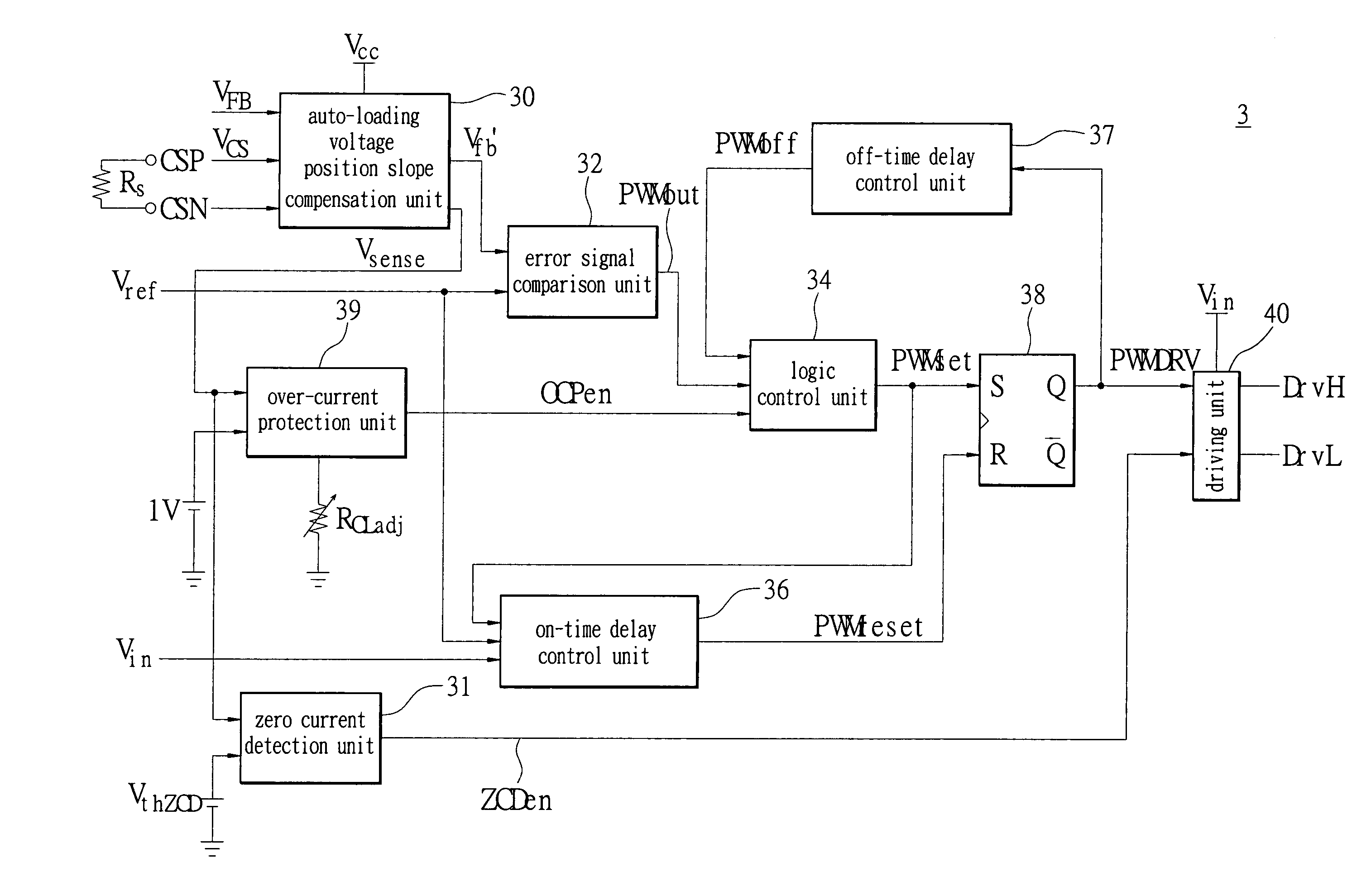
[0036]Please refer to FIG. 5, which a circuit structure diagram of the high-speed PWM control apparatus with adaptive voltage position used in a buck voltage DC—DC converter circuit of the present invention. The present invention integrates an active loading detection with the high-speed PWM control apparatus with adaptive voltage position 3. The present invention obtains a current detection signal from a detection resistor Rs via two signal inputs CSN and CSP and obtains a voltage feedback signal Vfb from an output divide-voltage resistor R2 via a feedback port FB (when the output voltage Vout is low, the voltage feedback signal Vfb is obtained directly from the output voltage Vout). In the high-speed PWM control apparatus with adaptive voltage position 3, the voltage feedback signal Vfb is added with a compensation voltage signal Vslope to generate a feedback voltage adjusting signal Vfb′. A port FAdj of the high-speed PWM control apparatus with adaptive voltage position 3 is conn...


PUM


Abstract

A high-speed PWM control apparatus with adaptive voltage position and a driving signal generating method thereof is provided. The present invention automatically detects a change in the loading and adjusts the voltage position instantaneously for stabilizing the voltage and reducing the loading output power consumption. The present invention does not require a clock signal to generate a driving signal and does not require an error amplifier to control the modulation. Therefore, the present invention has a fast transient response that responds to the change of the loading instantaneously and has a stabilizing effect. When the apparatus is on a continuous conduction mode (CCM), the switching frequency of the controller is still fixed even though the input voltage Vin and the output voltage Vout are changed. The electrical-magnetic noise disturbance is improved.

Description

BACKGROUND OF THE INVENTION[0001]1. Field of the Invention[0002]The present invention relates to a fast transient response PWM control apparatus for a voltage regulator with adaptive voltage position and its driving signal generating method. In particular, this invention is used for a switching DC—DC power converter apparatus. The present invention detects changes in the loading instantaneously and creates a response rapidly to stabilize the output voltage.[0003]2. Description of the Related Art[0004]Control methods for a switching DC—DC power converter are typically divided into two types. One uses clock signals as the frequency for controlling the switching of the power devices. Another one does not use a clock signal to control the switching of the power devices in the DC—DC converter. When using a clock signal, the frequency of the switching signal of the DC—DC converter is fixed and is the same as the frequency of the clock signal. The duty cycle (D) of the switching signal, de...

Claims


Application Information

Patent Timeline
Patent Type & Authority Patents(United States)
IPC IPC(8): G05F1/40
CPCH02M1/44H02M3/157H02M3/1563
Inventor WU, CHUNG-CHENGHUANG, QINDUAN, XIAO-MING
Owner NIKO SEMICON
Why Eureka
Try Eureka