Image pickup apparatus containing light adjustment portion with reflection of a portion of light onto adjacent pixels

a pickup apparatus and light adjustment technology, applied in the field of image pickup apparatus, can solve the problems of low grade, high price of birefringent plate, misregistration, etc., and achieve the effect of less moiré and high grad

Inactive Publication Date: 2006-09-19
CANON KK
View PDF15 Cites 55 Cited by
  • Summary
  • Abstract
  • Description
  • Claims
  • Application Information

AI Technical Summary

Benefits of technology

[0019]The present invention has been devised in view of the above and other drawbacks, and it is an object of the present invention to realize an image pickup apparatus that obtains a high grade image with less moiré without requiring an expensive optical lowpass filter.

Problems solved by technology

However, the above-mentioned conventional technique has the following problems.
However, since digital filtering that is the fourth process is applied to an image output that has already been subjected to sampling by the image pickup element, it is unnecessary to take into account a high frequency wave exceeding the Nyquist frequency.
Thus, the birefringent plate becomes very expensive.
In addition, the diffraction grating is also expensive because a highly precise fine structure is required.
However, since image shift depending on an object distance occurs due to the compound eye, a sampling pitch of an object image becomes unequal in a distance other than a reference object distance.
That is, misregistration occurs.
Therefore, a predetermined image performance is not always realized regardless of object conditions.
However, since a shape of the pixels becomes complicated, an extremely fine structure is required.
In addition, since each pixel divides a plane, an effect is not easily realized if an object image projected on the pixels has, for example, a slant line along the dividing line.
However, ⅓ of visible light is not photoelectrically converted and is not effectively utilized in an image pickup element using complementary color filters.
In this way, the conventional image pickup element of the single plate type using either primary color filters or complementary color filters has a bad light utilization efficiency because an image pickup surface is divided by color filters.
If it is attempted to make a sensor of a small pixel pitch, an extremely fine structure is required of the color pixels, but there is a limit in making the pixel pitch smaller.

Method used


Image

  • Image pickup apparatus containing light adjustment portion with reflection of a portion of light onto adjacent pixels
  • Image pickup apparatus containing light adjustment portion with reflection of a portion of light onto adjacent pixels
  • Image pickup apparatus containing light adjustment portion with reflection of a portion of light onto adjacent pixels

Examples


first embodiment

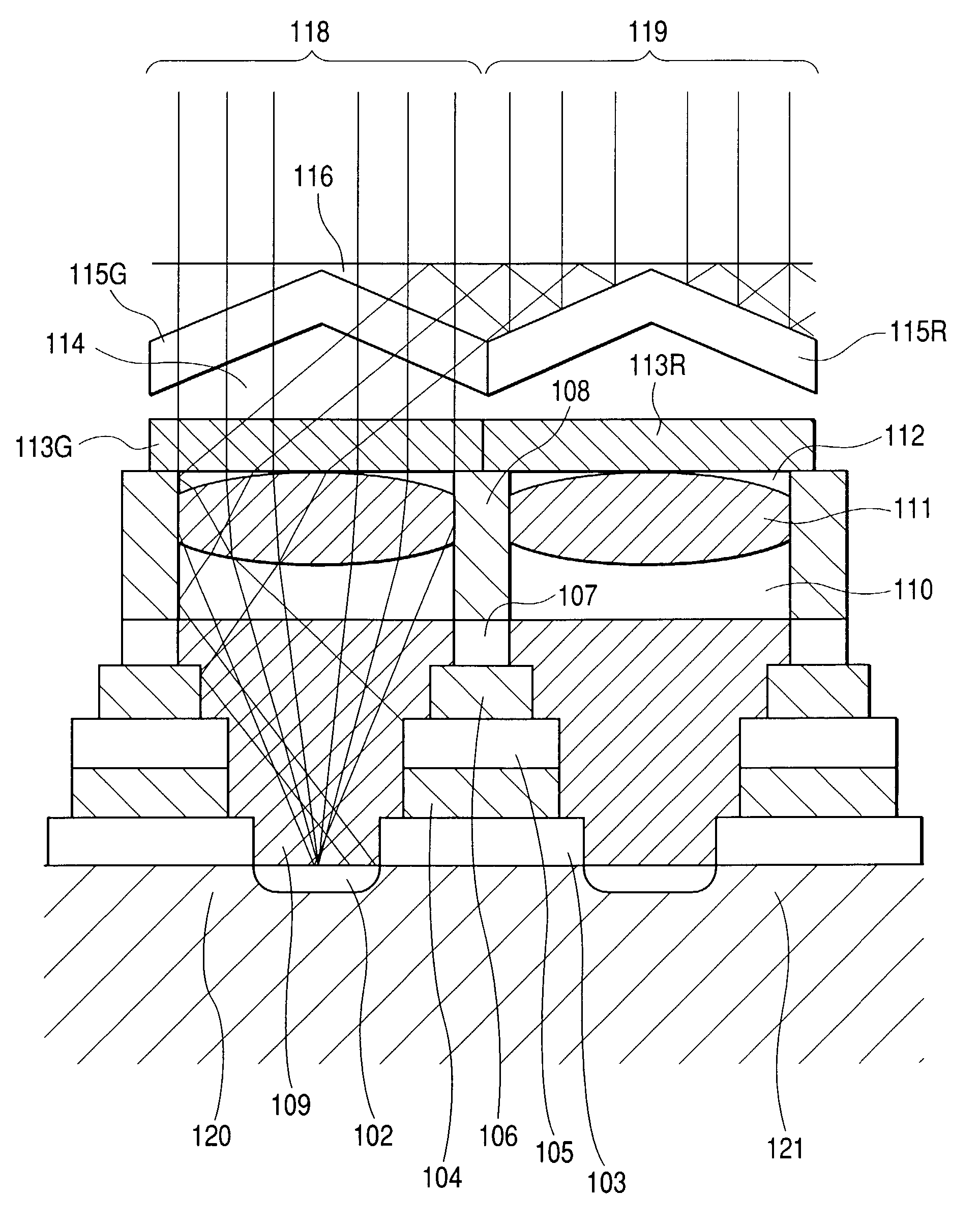
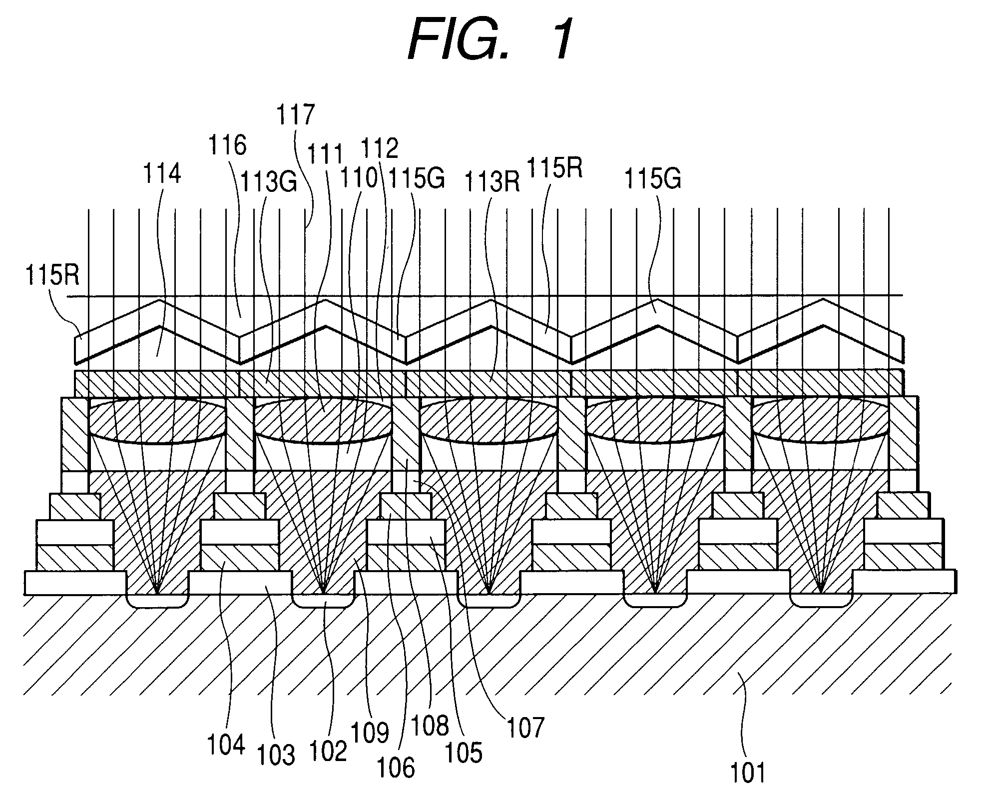
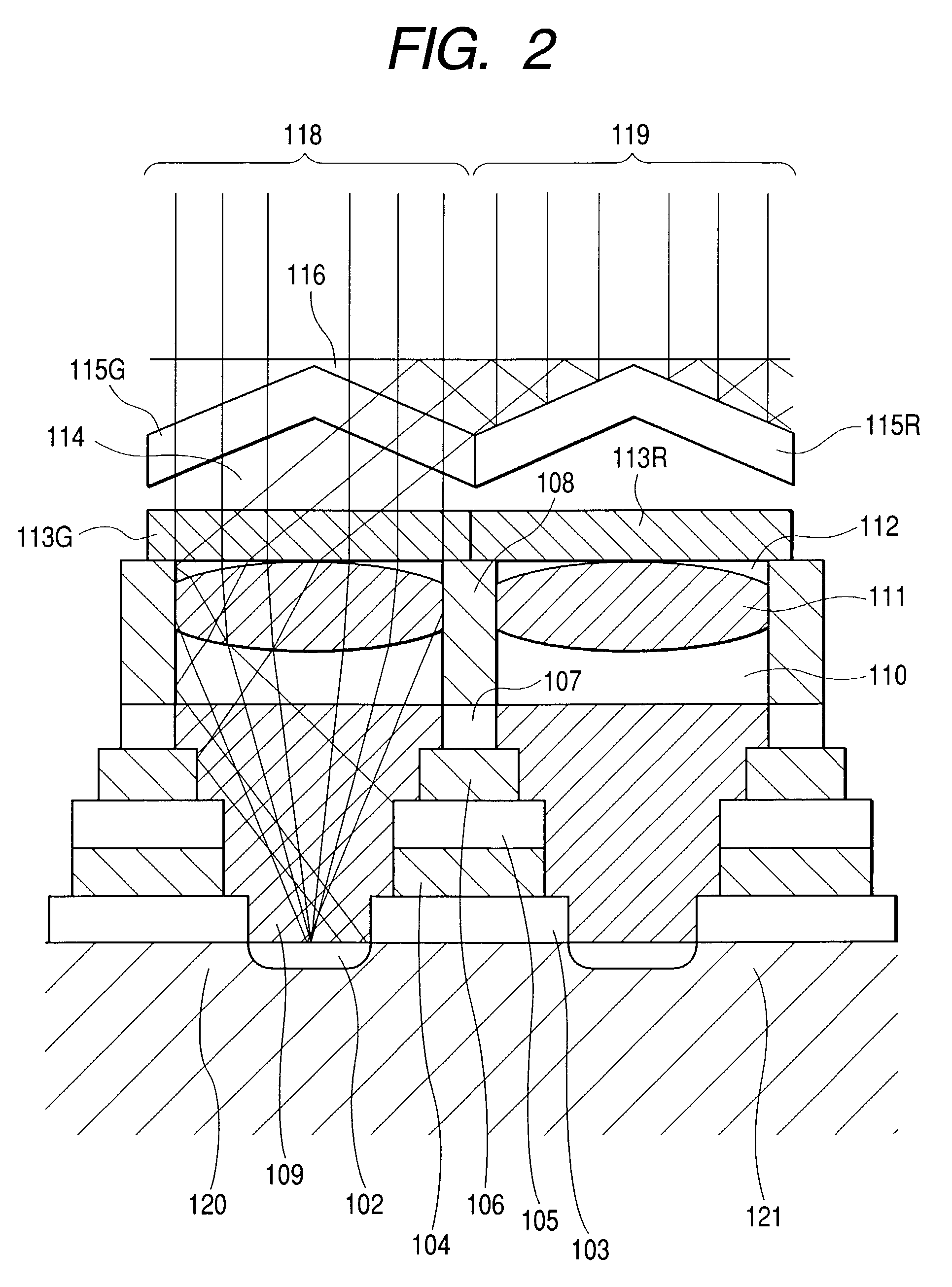
[0054]FIGS. 1 to 14 are views or graphs for explaining a first embodiment in accordance with the present invention. First, FIG. 1 is a sectional view of an image pickup element and FIG. 2 is an enlarged sectional view of the image pickup element. FIGS. 1 and 2 show a state in which object light is incident on a pixel column, in which G pixels and R pixels having different spectral sensitivity characteristics are alternately arranged as in the Bayer array or the like, and reaches photoelectric conversion areas. Note that, in the Bayer array, pixels are regularly arranged with 2×2 R, G, G and B pixels columns as one unit.

[0055]In FIGS. 1 and 2, reference numeral 101 denotes a silicon substrate; 102, photoelectric conversion areas; 103, 105, 107, 110 and 112, low refraction material layers; 104, 106 and 108, wiring layers of metal such as aluminum; and 109 and 111, high refraction material layers. Silicon oxide (SiO2) having an index of refraction of 1.45 and silicon nitride (Si3N4) ha...

second embodiment

[0079]FIGS. 15 and 16 are views for explaining a second embodiment in accordance with the present invention. FIG. 15 is a plan view showing an arrangement of pixels and a shape of microlenses. FIG. 16 is a plan view showing an effective light receiving opening of each pixel.

[0080]In these figures, reference numeral 201 denotes microlenses and 202 denotes effective light receiving openings. An arrangement of pixels is 45 degrees rotated from the Bayer array. Therefore, 2×2 R, G, G and B pixel columns are one unit. As disclosed in JP 2000-184386 A, an image pickup element of such an arrangement is preferable for obtaining an image of higher resolution while suppressing increase of the number of pixels.

[0081]As shown in FIG. 15, each of the pixel openings constituted by the microlens 201 is a square having four sides slanted in a 45 degree direction and is arranged densely with being in contact with adjacent pixels. This image pickup element also has the structure shown in FIG. 2 as in...

third embodiment

[0085]FIGS. 19 to 21 are views for explaining a third embodiment in accordance with the present invention. FIG. 19 is a plan view of an image pickup element having R, G and B stripe filters 301. FIG. 20 is a perspective view of an interference filter layer. FIG. 21 is a plan view showing an effective light receiving opening of each pixel.

[0086]In the image pickup element having the R, G and B stripe filters 301, a lengthwise pixel column having an R filter, a lengthwise pixel column having a G filter and a lengthwise pixel column having a B filter are repeated in sideways. That is, 1×3 R, G and B pixels are one unit having a regular arrangement, and among adjacent four pixels, pixels in the vertical direction are pixels of an identical filter and pixels in the horizontal direction are pixels of different filters. Even in such a structure, the pixel structure shown in the first embodiment is effective in terms of adjusting an MTF of a pixel. However, it is preferable to optimize the ...


PUM


Abstract

An image pickup apparatus comprises a plurality of photoelectric conversion areas, and a light adjustment area including a first transmission portion for transmitting light which is provided in association with a first photoelectric conversion area included in the plurality of photoelectic conversion areas and a second transmission portion for transmitting light which is provided in association with a second photoelectric conversion area included in the plurality of photoelectric conversion areas. The light adjustment area is configured to cause a part of light incident on the second transmission portion to be incident on the first transmission portion.

Description

BACKGROUND OF THE INVENTION[0001]1. Field of the Invention[0002]The present invention relates to an image pickup apparatus for picking up an object image.[0003]2. Related Background Art[0004]Conventionally, in forming a color image, an image pickup technique is widely used which picks up an object image by a single image pickup element in which pixels each provided with any one of primary color filters of red (R), green (G) and blue (B) are arranged in mosaic and generates luminance information and color information corresponding to the number of pixels by subsequent signal processing. In many cases, a color filter array of the image pickup element used in this technique is the Bayer array. This image pickup technique can realize significant cost reduction without degrading quality of an image so much compared with an image pickup method of a three plate system that separates an object image into R, G and B in advance using a beam splitter for color separation and picking up an imag...

Claims


Application Information

Patent Timeline
Patent Type & Authority Patents(United States)
IPC IPC(8): H04N5/225H01L31/0232H01L31/062H01L31/113H04N9/07H01L27/14H01L27/146H04N5/335H04N5/369H04N5/378H04N9/04
CPCH01L27/14603H01L27/14621H01L27/14625H04N9/045H01L27/14629H01L27/14645H01L27/14627H04N25/6153H04N25/134
Inventor SUDA, YASUO
Owner CANON KK
Why Eureka
Try Eureka