Method and apparatus for low temperature pyrometry useful for thermally processing silicon wafers

a pyrometry and low temperature technology, applied in lighting and heating apparatus, muffle furnaces, furnaces, etc., can solve the problems of thermal and electronic noise, ineffective conventional pyrometry, and inability to accurately describe the rtp chamber at lower temperatures

Active Publication Date: 2006-09-26
APPLIED MATERIALS INC
View PDF9 Cites 62 Cited by
  • Summary
  • Abstract
  • Description
  • Claims
  • Application Information

AI Technical Summary

Benefits of technology

[0020]The transmission pyrometry is advantageously performed knowing the general characteristics relating power delivered to the radiant heating lamp or other electrical characteristic thereof, the wafer temperature, and the photocurrent of a transmission pyrometer. In one method of compiling the characteristics, the photocurrent can be calculated within a constant from lamp and detector characteristic. A two-dimension table may be filled with the unnormalized photocurrent as function of wafer and lamp temperature or other methods of retrieving a known characteristic may be used. A initial measurement of the photocurrent at a known temperature of the wafer allows the tabular data to be normalized for the wafer being processed. Thereafter, when the pyrometer photocurrent is measured at a known lamp temperature or resistance, the table is consulted to obtain the corresponding wafer temperature.

Problems solved by technology

The described RTP chamber, however, suffers some drawbacks in its use at lower temperatures.
However, pyrometry is generally used for measuring high temperatures, for example, above 500 or 800° C. In the configuration of RTP reactors in which the chamber parts are relatively warm and there is light leakage from radiant bulb, conventional pyrometry is relatively ineffective at wafer temperatures of less than about 450° C. Photocurrents of a conventional pyrometer exposed to a 350° C. body are in the neighborhood of 0.8 pA, a level easily overwhelmed by thermal and electronic noise in a typical RTP environment.
As a result, temperature gradients or excessive heating rates may occur.
The wafer may become misshapen during the pre-heating into a domed or potato-chip shape that prevents effective RTP at yet higher temperatures.
Except in the situation of very long production runs, it is infeasible to optimize for each level of each chip design.
Generally, this approach has proven unsatisfactory and results in uncertain pre-heating rates and other uniformities requiring yet further adjustments.

Method used


Image

  • Method and apparatus for low temperature pyrometry useful for thermally processing silicon wafers
  • Method and apparatus for low temperature pyrometry useful for thermally processing silicon wafers
  • Method and apparatus for low temperature pyrometry useful for thermally processing silicon wafers

Examples


Embodiment Construction

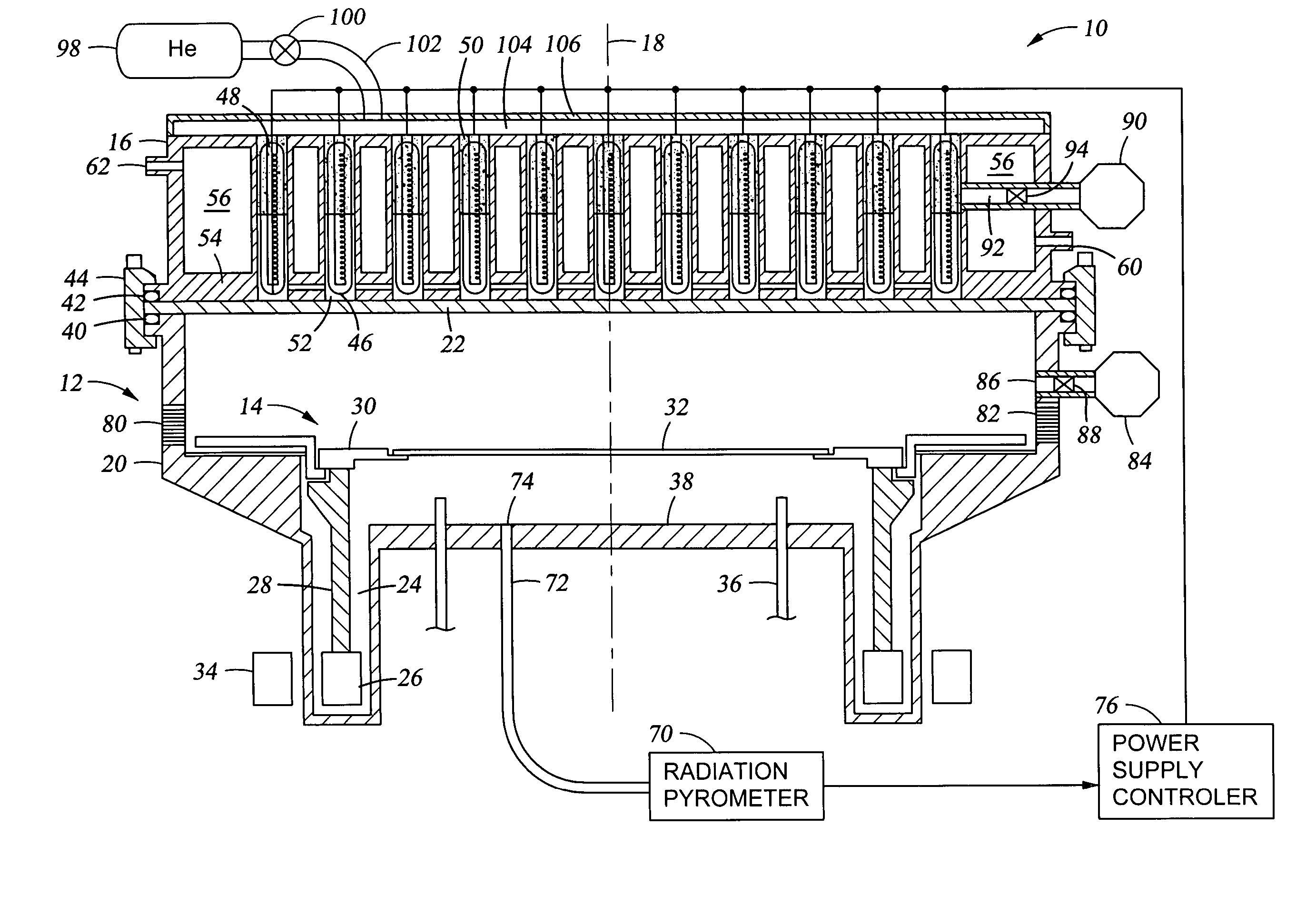
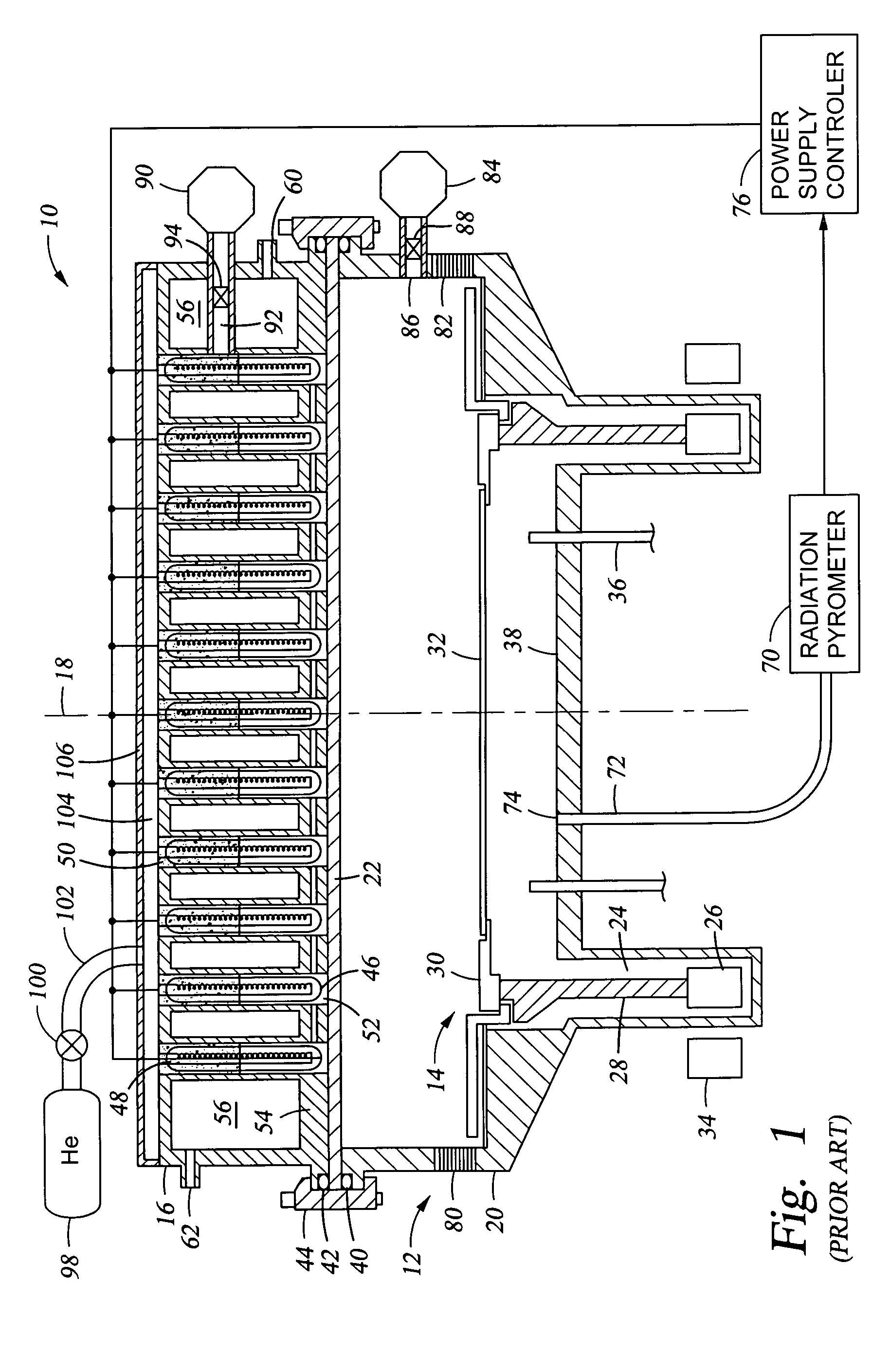
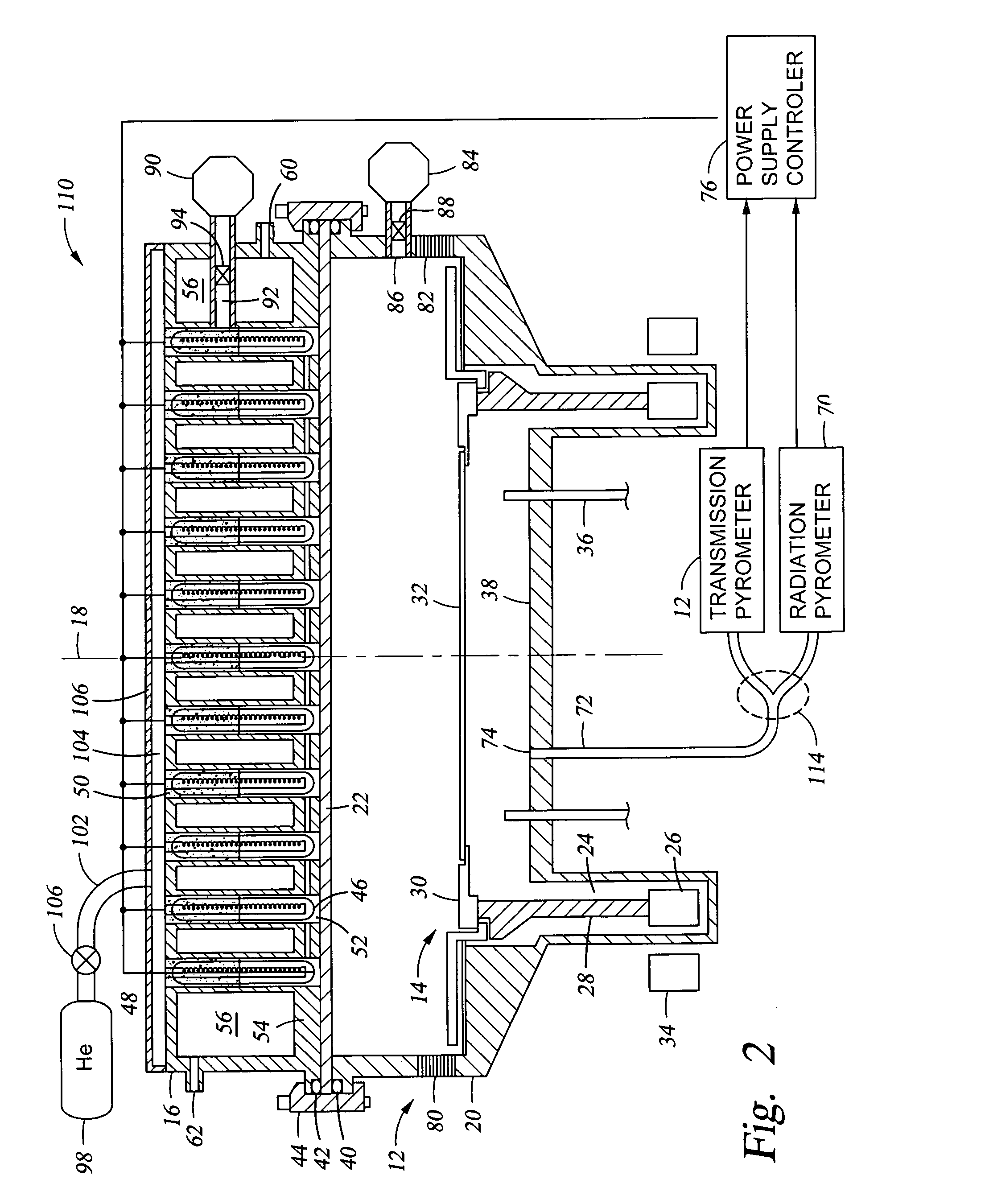
[0030]One embodiment of a rapid thermal processing (RTP) chamber 110 of the invention is schematically illustrated in the cross-sectional view of FIG. 2. It includes at least one transmission pyrometer 112. Although some aspects of the invention can be practiced with transmission pyrometry alone, advantageously the inventive chamber 110 additionally includes one or more radiation pyrometers 70. The two pyrometers 70, 102 may be included in a single system receiving optical radiation from the light pipe 72 and an optical splitter 104 divides the received radiation between the two pyrometers 70, 102. As mentioned previously, the radiation pyrometer 70 includes a narrow band filter at a sub-micron wavelength, that is, passing photons having energies greater than the silicon band gap. The radiation pyrometer 70 is thus effective at measuring the blackbody radiation temperature at the back side of the wafer 32 since the silicon wafer 32 blocks the shorter wavelength light from the lamps ...


PUM

PropertyMeasurementUnit
temperaturesaaaaaaaaaa
band gapaaaaaaaaaa

Abstract

A rapid thermal processing (RTP) system including a transmission pyrometer monitoring the temperature dependent absorption of the silicon wafer for radiation from the RTP lamps at a reduced power level. A look-up table is created relating unnormalized values of photodetector photocurrents with wafer and radiant lamp temperatures. A calibrating step measures the photocurrent with known wafer and lamp temperatures and all photocurrents measured thereafter are accordingly normalized. The transmission pyrometer may be used for closed loop control for thermal treatments below 500° C. or used in the pre-heating phase for a higher temperature process including radiation pyrometry in closed loop control. The pre-heating temperature ramp rate may be controlled by measuring the initial ramp rate and readjusting the lamp power accordingly. Radiation and transmission pyrometers may be included in an integrated structure with a beam splitter dividing radiation from the wafer.

Description

FIELD OF THE INVENTION[0001]The invention relates generally to thermal processing of semiconductors. In particular, the invention relates to rapid thermal processing (RTP) of silicon wafers.BACKGROUND ART[0002]Rapid thermal processing (RTP) is a term applied to several types of thermal processes including annealing, dopant activation, oxidation, and nitridation among others. The aforementioned processes are typically performed at relatively high temperatures above about 1000° C. It can be further applied to etching and chemical vapor deposition in the presence of precursor or etching gases. The latter processes are conventionally performed in an RTP chamber at somewhat lower temperatures of between 500° and 800° C. RTP typically depends upon an array of high-intensity incandescent lamps fit into a lamphead and directed at the substrate being processed. The lamps are electrically powered and can be very quickly turned on and off and a substantial fraction of their radiation can be di...

Claims


Application Information

Patent Timeline
Patent Type & Authority Patents(United States)
IPC IPC(8): F27D11/00
CPCF27B5/04F27B17/0025H05B3/68H01L21/67115H01L21/67248F27D21/0014A21B1/00F27D11/00H01L21/324
Inventor HUNTER, AARONRAMANUJAM, RAJESH S.RAMACHANDRAN, BALASUBRAMANIANTANASA, CORINA ELENADIXIT, TARPAN
Owner APPLIED MATERIALS INC
Why Eureka
Try Eureka