DC-DC converter

Inactive Publication Date: 2006-09-26
MURATA MFG CO LTD
View PDF19 Cites 23 Cited by
  • Summary
  • Abstract
  • Description
  • Claims
  • Application Information

AI Technical Summary

Benefits of technology

[0017]According to a preferred embodiment of the present invention, a switching power supply unit includes a plurality of switching power supply circuits that are connected in parallel with each other. The total output of the switching power supply circuits is supplied to a load. Each switching power supply circuit includes an overcurrent detection circuit section for directly or indirectly detecting an overcurrent state of the current that is output to the load, and an overcurrent protection circuit section for performing a hiccup-mode overcurrent protection operation in which the circuit operation is cyclically stopped and restarted upon the detection of an overcurrent state. The switching power supply unit further includes a device for matching hiccup-mode restart timings of the switching power supply circuits when each switching power supply circuit performs the hiccup-mode overcurrent protection operation using the corresponding overcurrent protection circuit section. According to this preferred embodiment of the present invention, it is possible to prevent problems caused by mismatching of the restart timings since the hiccup mode restart timings can be matched. Thus, the present preferred embodiment of the present invention offers an advantage of solving a problem in that, variations in C and R components of a time constant circuit, which determines time from the stopping of the switching operation due to overcurrent to the restarting thereof cause variations in time from the stopping of the operation to the restarting thereof for each switching power supply circuit. This displaces the restart timings, and each power supply circuit cannot immediately return to a normal state after load short circuiting is eliminated (i.e., after an overcurrent state is eliminated). Further, the present preferred embodiment of the present invention offers the advantage of solving a problem in that a load malfunctions since the mismatched restart timings cause the voltage waveform to become a step-up and step-down form when the circuit returns to a normal state.
[0018]Preferably, each switching power supply circuit includes a switching controller for controlling the stopping and the starting of the circuit operation and the overcurrent protection circuit

Problems solved by technology

In addition, for an insulated switching power supply circuit using a synchronous rectifier for rectifying the output current, there is a problem in that, when overcurrent protection is performed in an output voltage drop mode during load short-circuiting, the power supply for driving the synchronous rectifier cannot be secured, thereby heating the synchronous rectifier Thus, an overcurrent protection operation may he performed by combining an output voltage drop mode with another synchronous rectifier protection mode.
In this manner, the deviation of the restart timings due to the difference between waiting times of the switching

Method used


Image

  • DC-DC converter
  • DC-DC converter
  • DC-DC converter

Examples


Example

[0030]Preferred embodiments according to the present invention will now be described with reference to the accompanying drawings.

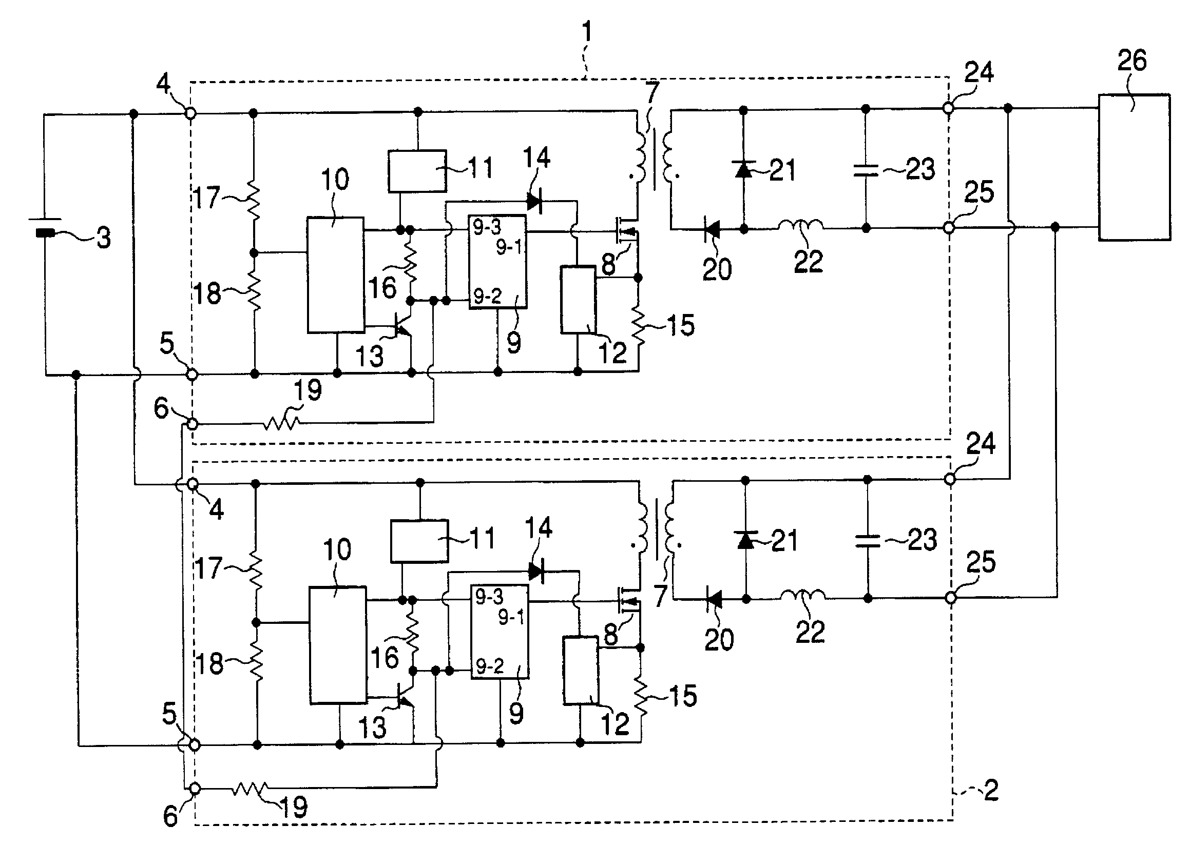
[0031]FIG. 1 shows the circuit configuration of a switching power supply unit of a first preferred embodiment of the present invention. The first preferred embodiment corresponds to a first aspect of the present invention. In FIG. 1, reference numeral 1 indicates a switching power supply circuit, 2 is another switching power supply circuit, 3 is a DC input power supply, 4 is a positive input terminal, 5 is a negative input terminal, 6 is a simultaneous starting terminal that serves as a connection for simultaneous startup, 7 is a transformer, 8 is a main switch, and 9 is a PWM control IC that functions as a switching controller for the main switch 8. Reference numeral 9-1 in the PWM control IC 9 is a gate driving terminal for the main switch 8, 9-2 is an ON / OFF control terminal, and 9-3 is a terminal for receiving the supply of a control circuit drive volt...


PUM


Abstract

A switching power supply unit includes an overcurrent protection circuit section and a latch-stop release signal output circuit section. The overcurrent protection circuit section performs an overcurrent protection operation for latching and stopping the switching operation of a main switch during an overcurrent state. The latch-stop release signal output circuit section outputs a signal, only in a predetermined latch-stop release period, for releasing the latch stop after a certain waiting time has elapsed from the time of the latch stop. This arrangement can virtually perform a hiccup-mode overcurrent protection operation at the time of overcurrent, and expands the scope of application of a switching power supply unit. Switching power supply circuits are interconnected by simultaneous starting connections. Switching controllers for the main switches are connected to match hiccup mode restart timings.

Description

BACKGROUND OF THE INVENTION[0001]1. Field of the Invention[0002]The present invention relates to a switching power supply unit having a function of protecting against output overcurrent.[0003]2. Description of the Related Art[0004]Typically, switching power supply units include a circuit having an overcurrent protection function for preventing load circuit components from being broken, emitting smoke, or being ignited due to output overcurrent during short-circuiting of a load. The switching power supply circuits for performing overcurrent protection are provided with a device for detecting overcurrent. Various circuit systems are known for detecting overcurrent. Examples include a system in which a current detection element, such as a current transformer or resistor, is inserted in an output current path to directly detect the output current. For an insulated switching power supply circuit having a transformer, there is a system in which a current detection element, such as a curre...

Claims


Application Information

Patent Timeline
IPC IPC(8): H02H9/02H02H7/20H02H3/06H02H7/12H02J1/10H02M3/28H02M3/335
CPCH02H3/06H02H7/1213H02M3/33507H02M1/36H02M1/32
Inventor MATSUMOTO, TADAHIKO
Owner MURATA MFG CO LTD
Why Eureka
Try Eureka