Redundant WDM transmission system optical receiver with reduced variable optical attenuators and/or variable dispersion compensation modules

a transmission system and optical receiver technology, applied in the field of optical receivers, can solve the problems of unreasonable shortcoming of massive system, system size too large, communication network greatly impaired, etc., and achieve the effect of improving transmission quality and suppressing the redundancy of the wdm transmission line in the overall optical receiver

Inactive Publication Date: 2006-09-26
FUJITSU LTD
View PDF3 Cites 10 Cited by
  • Summary
  • Abstract
  • Description
  • Claims
  • Application Information

AI Technical Summary

Benefits of technology

[0011]The present invention is made to overcome the foregoing shortcomings. It is therefore an object of the present invention to provide an optical receiver which is configured to keep the redundancy of the WDM transmission line entailed in the overall optical receiver suppressed and improve the quality of transmission even in switching the transmission line.

Problems solved by technology

Since the WDM transmission treats a large amount of data to be transmitted through one fiber, if some accident such as a disaster or a malicious deed is brought about in the fiber facility, the communication network is far more greatly impaired.
However, in building the redundant configuration of the conventional WDM system, the redundant provision of switches for switching a transmission line in the transmitting station and the receiving station of the WDM transmission system, that is, the redundantly switching of a transmission line for each signal wavelength makes the system too large in scale because the system needs the same number of switches and transponders as the number of signal wavelengths to be treated.
The massive system has a shortcoming that it is not reasonable in a variety of factors such as initial cost, running cost, maintenance, and reliability.
This provision of the switching functions also has a shortcoming that the receive amplifier needs a considerable length of time until the amplifier enters into a stable state after switched and thereby the main signal stays in an erroneous state for a relatively long time, because the amplifier greatly varies its dynamic range and makes its transient response too large.

Method used


Image

  • Redundant WDM transmission system optical receiver with reduced variable optical attenuators and/or variable dispersion compensation modules
  • Redundant WDM transmission system optical receiver with reduced variable optical attenuators and/or variable dispersion compensation modules
  • Redundant WDM transmission system optical receiver with reduced variable optical attenuators and/or variable dispersion compensation modules

Examples


Embodiment Construction

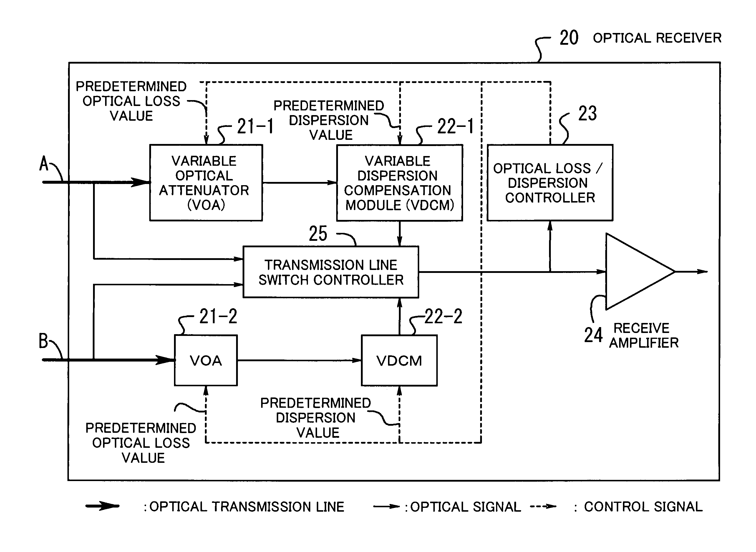
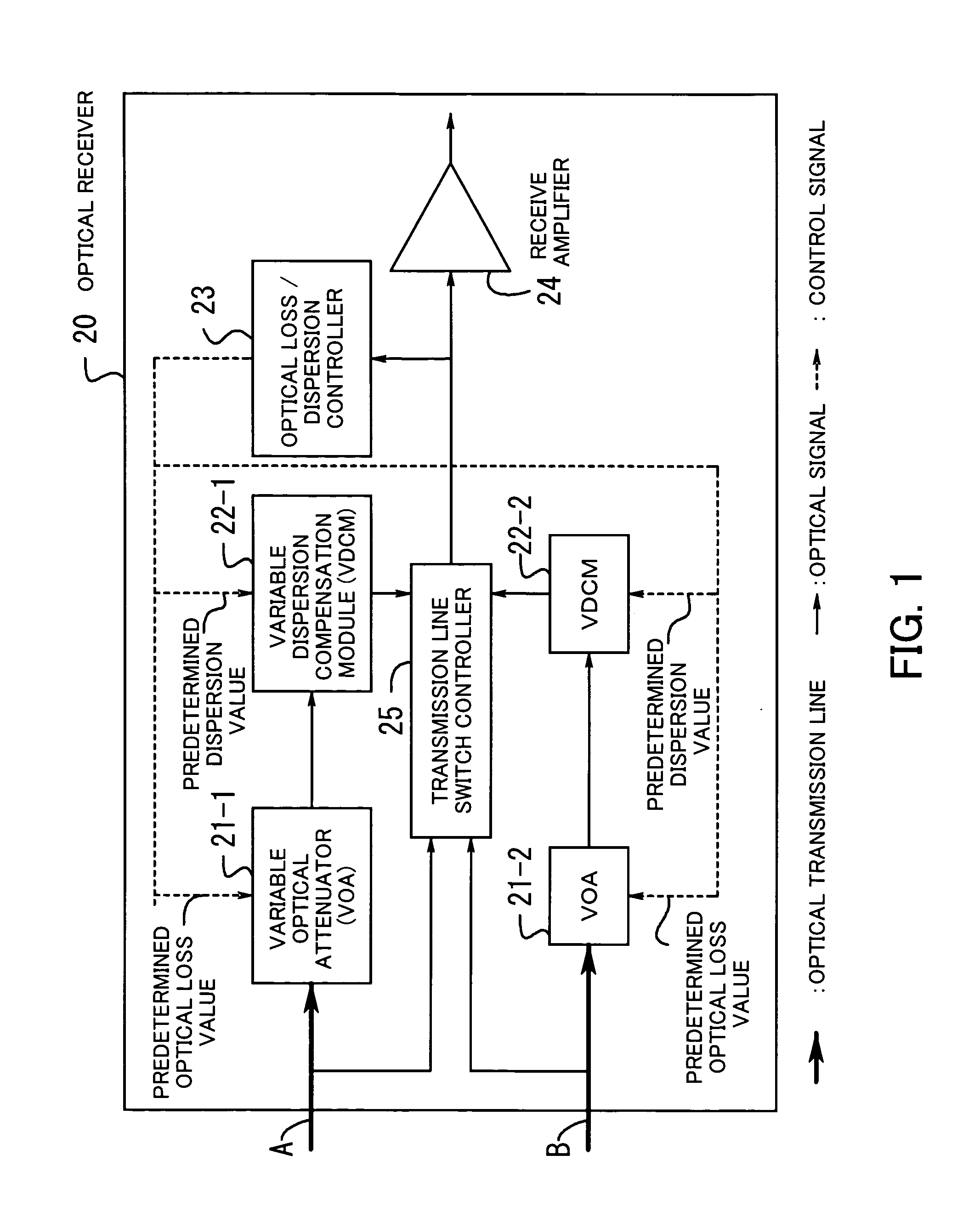
[0022]Hereafter, the embodiments of the present invention will be described with reference to the appended drawings. FIG. 1 illustrates the concept of the optical receiver according to the present invention. An optical receiver 20 is installed on the side of a receiving station of the system with the redundant configuration of optical transmission lines (the redundant provision of two optical transmission lines A and B in FIG. 1).

[0023]Variable optical attenuators 21-1 and 21-2 (often referred simply to as VOAs) are installed respectively on the optical transmission lines A and B prepared for the redundant configuration. These VOAs control an optical loss value of each line based on a predetermined optical loss value. Variable dispersion compensation modules 22-1 and 22-2 (often referred simply to as a VDCM) are installed respectively on two optical transmission lines A and B prepared for the redundant configuration. The VDCM controls the wavelength dispersion value for the correspo...


PUM


Abstract

An optical receiver including a variable optical attenuator for controlling an optical loss value for each optical transmission line based on a predetermined optical loss value; a variable dispersion compensation module for controlling a wavelength dispersion value for each optical transmission line based on a predetermined dispersion value; an optical loss / dispersion controller for measuring the optical loss value and the wavelength dispersion value of every optical transmission line, outputting these values so that they are equal in all the optical transmission lines, and controlling the attenuator and the module based on the outputted predetermined values; a receive amplifier for receiving the optical signal whose light level is kept constant and amplifying the signal; and, a transmission line switch control module is provided for switching a working transmission line into a protection line if the optical signal level of the working line is lower than a threshold value.

Description

[0001]This application is a continuing application, filed under 35 U.S.C. §111(a), of International Application PCT / JP2002 / 011901, filed Nov. 14, 2002.BACKGROUND OF THE INVENTION[0002](1) Field of the Invention[0003]The present invention relates to an optical receiver, and more particularly to an optical receiver which is configured to receive an optical signal.[0004](2) Description of the Related Art[0005]With recent variety of data flowing through a communication network and recent increase of users of the internet, the amount of data flowing through the network is growing more and more. To cope with the growth, it has been requested to expand the capacity and the scale of the network. In the field of long-distance communications, therefore, for the purpose of expanding the capacity of the network through the use of the existing optical fiber facility, the main focus is placed on the WDM (Wavelength Division Multiplex) transmission system.[0006]This WDM transmission system is a sy...

Claims


Application Information

Patent Timeline
Patent Type & Authority Patents(United States)
IPC IPC(8): H04B10/06H01S3/00H04B10/08H04B17/00H04J14/02H04B10/03H04B10/032H04B10/07H04B10/077H04B10/079H04B10/2507H04B10/2513H04J14/00
CPCH04B10/07955H04B10/25133H04B2210/252
Inventor KAWASUMI, TATSUYA
Owner FUJITSU LTD
Why Eureka
Try Eureka