Transverse cavity device and method

a transverse cavity and device technology, applied in the field of bone compression fracture treatment, can solve the problems of reducing the structural integrity of the vertebrae, affecting the patient, and reducing the height of the vertebrae, so as to increase the area of the “footprint” and reduce the total distraction for

Inactive Publication Date: 2006-10-03
SPINEWAVE
View PDF39 Cites 208 Cited by
  • Summary
  • Abstract
  • Description
  • Claims
  • Application Information

AI Technical Summary

Benefits of technology

[0011]In contrast to the prior art, the devices and methods of the present invention are used to create an initial cavity in the vertebral body that has a controlled shape and location. FIG. 13 represents a prior art procedure where a narrow and small cavity 17 is filled with a balloon and the overall “footprint” is small so that the total distraction force is also small. FIG. 14 represents a cavity created according to the invention filled with a balloon to apply distraction force. In this figure, the increased area of the “footprint” of the transverse cavity 18 permits greater distraction force per unit balloon pressure.
[0015]Once a fracture is reduced, the bone cavity may be filled with a bone filler material such as bone cement, allograft, or synthetic bone substitutes. The filler acts to increase the stability and strength of the bone. In some interventions, the filler may be combined with bone growth factors (BMPs, cell therapy, autologous growth factors) to accelerate bone remolding and increase the amount of bone remodeling. Likewise, other drugs or therapies (including but not limited to antibiotics, chemotherapy, and other drug therapies) may be combined with the bone filler.

Problems solved by technology

However, there are many disease states and aging processes that impact the patient.
Osteoporosis and metastatic disease reduce the structural integrity of the vertebral bodies, predisposing them to fracture.
Vertebral fractures can lead to loss of vertebral height, which can exacerbate existing neurological conditions or predispose the spine to other symptoms.
Back pain often results from these conditions.
Generally, if not treated, fractures and loss of height result in a cascade of injury which is undesirable.
The transverse cavity reduces contact stress in supporting bone and decreases the likelihood of cancellous compaction associated with prior art techniques.
As a result, these devices do not expand in a predictable manner, often expanding vertically before expanding horizontally (transverse).
Rather than consistently reducing the fracture, these techniques often crush the cancellous bone, creating an expanded cavity without necessarily reducing the fracture or restoring the natural anatomy.

Method used


Image

  • Transverse cavity device and method
  • Transverse cavity device and method
  • Transverse cavity device and method

Examples


Embodiment Construction

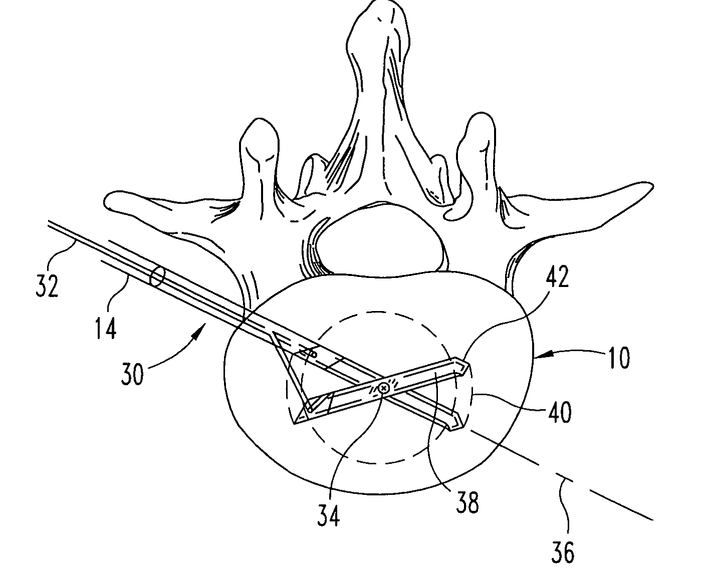
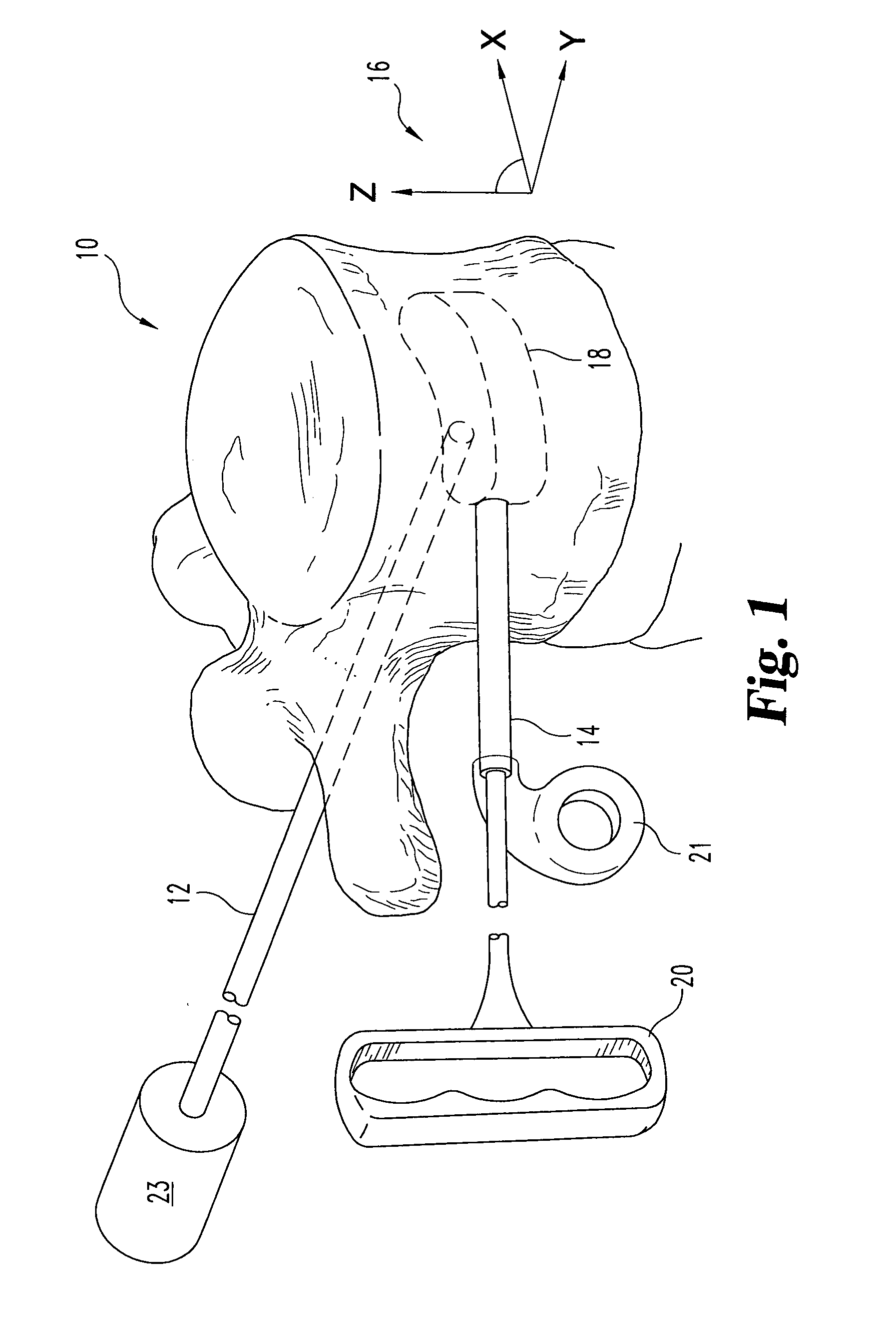
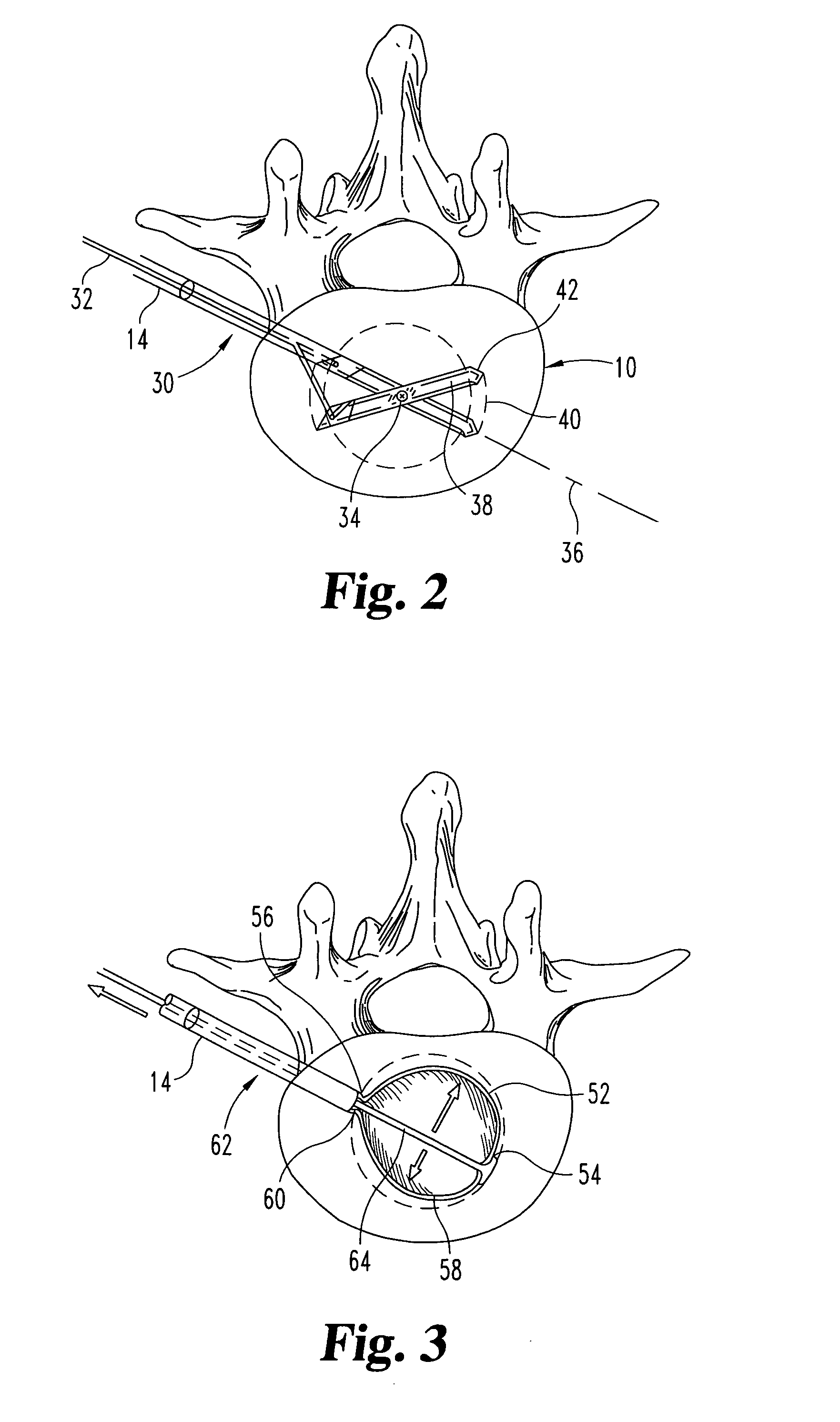
[0034]FIG. 1 is a phantom view of a vertebral body showing a transverse cavity 18 and a coordinate system 16. This figure shows a vertebral body 10 in isolation. Two possible surgical entry points into the vertebral body contemplated within the scope of the invention are illustrated. One entry point is “transpedicular.” This approach is indicated by the physical location of tube 12, traveling through the pedicle into the vertebral body 10. Another approach is “extra-pedicular.” This access approach is illustrated by tool 14 entering the vertebral body at a location lateral of the transpedicular approach on the posterolateral corner of the vertebral body.

[0035]The typical surgery will include a small incision in the back adjacent to the vertebral body. Next, a small gauge needle or guide-wire is introduced to confirm proper positioning under fluoroscopy. Physicians typically utilize an 11-gauge needle for the transpedicular approach and a larger needle or tube (up to 6 mm ID) for the...


PUM


Abstract

The invention teaches the use of a surgical instrument for creating and preparing a cavity in a bony intervertebral body. Asymmetrical cutting structures selectively open a cavity which has a relatively large surface area in the vertical direction.

Description

CROSS-REFERENCE TO RELATED CASES[0001]The present case claims the benefit of, and incorporates by reference the following U.S. provisional applications:[0002]U.S. Provisional Patent Application Ser. No. 60 / 227,050 filed Aug. 21, 2000, entitled “Vertebroplasty Cavity Creation using an Expanding Tube” and,[0003]U.S. Provisional Patent Application Ser. No. 60 / 225,191 filed Aug. 14, 2000, entitled “Vertebral Body Expander.”FIELD OF THE INVENTION[0004]The present invention relates generally to the treatment of compression fractures in bones, and more specifically to a device and a method for cutting a “transverse” cavity in the bone as one part of a therapy.BACKGROUND OF THE INVENTION[0005]The human spine consists of a complex set of interrelated anatomic elements including a set of bones called vertebral bodies. Intervertebral discs separate most vertebral bodies. These discs includes a “spongy” nucleus pulpous surrounded by an annulus fibrosis “membrane.” The annulus fibrosis connects ...

Claims


Application Information

Patent Timeline
Patent Type & Authority Patents(United States)
IPC IPC(8): A61B17/00A61B17/32
CPCA61B17/320016A61B2017/00261A61B17/1671A61B17/8855
Inventor JOHNSON, WESLEYBARBER, DEBHEKTNER, THOMASFULLER, LARRYWALES, LAWRENCE W.
Owner SPINEWAVE
Why Eureka
Try Eureka