Friction fit target assembly for high power sputtering operation

a target assembly and high-power sputtering technology, applied in vacuum evaporation coating, non-electric welding apparatus, manufacturing tools, etc., can solve the problems of atoms or molecules of the target material to be sputtered, sputter target assemblies bonded by these methods can bow or bend at high sputtering temperature, and achieve low thermal conductivity, lower electrical conductivity, and high thermal conductivity

Inactive Publication Date: 2006-10-03
TOSOH SMD
View PDF9 Cites 31 Cited by
  • Summary
  • Abstract
  • Description
  • Claims
  • Application Information

AI Technical Summary

Benefits of technology

[0014]This low temperature bonding method enables consolidation of unconventional sputter target/backing plate assemblies. These sputter target/backing plate assemblies are unconventional insofar as they comprise targets and backing plates having dissimilar thermal expansion coefficients. For example, the difference between thermal expansion coefficients (TEC) of the target and backing plate may be greater than about 2.4,and preliminary data suggests that targets and backing plates having differences in TEC's of greater than 4 can also be successfully bonded and then used in high power 20–30 kw sputtering processes. In such processes, target temperatures may reach about 200°–300° C. An optional metal insert may be placed between the target and backing plate during the assembly process.
[0015]With respect specifically to Ti targets, diffusion bonding in prior art has been limited to conventional AL 6061 backing plates which have low thermal conductivity. In contrast, one such preferred assembly formed by the instant method is a Ti target or alloys thereof having an unconventional Cu-1% Cr backing plate and a Cu—Ni insert placed adjacent the peripheral boundary of the assembly.
[0016]In this preferred unconventional assembly, the Ti target and...

Problems solved by technology

Ion bombardment of the target not only causes atoms or molecules of the target material to be sputtered, but imparts considerable thermal energy to the target.
However, sputter target assemblies bonded by these methods can bow or bend at high sputtering temperatures, especially when a large difference exists between the coefficients of thermal expansion for the target and backing plate.
However, with ...

Method used


Image

  • Friction fit target assembly for high power sputtering operation
  • Friction fit target assembly for high power sputtering operation
  • Friction fit target assembly for high power sputtering operation

Examples


example 1

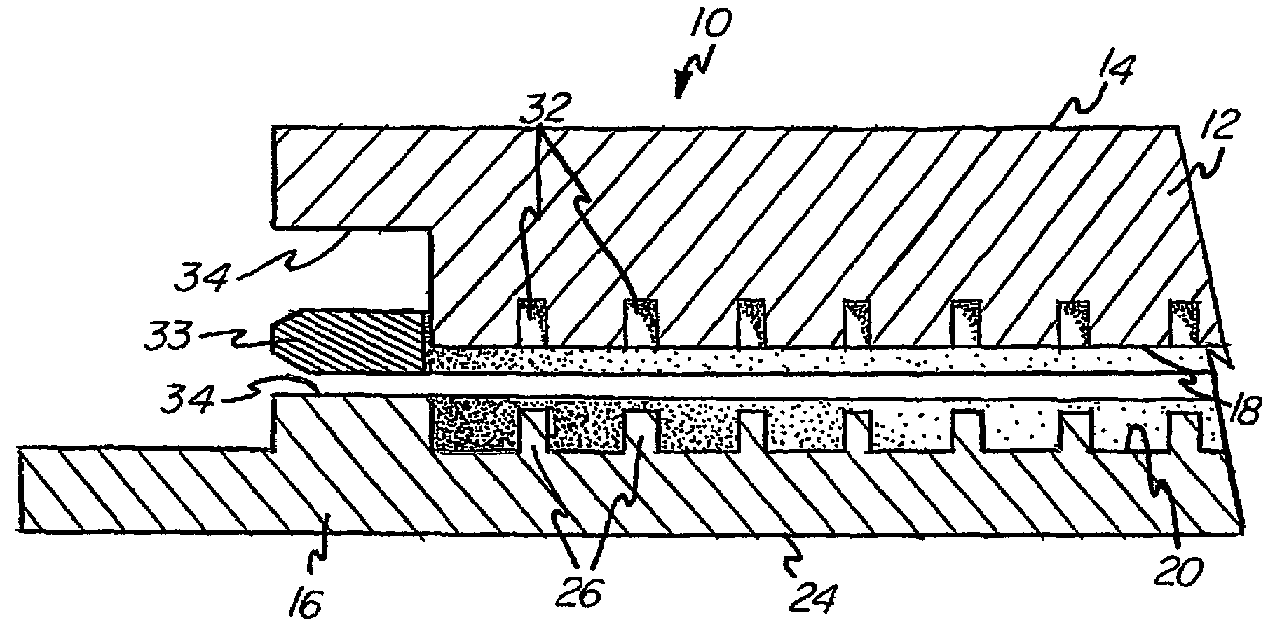
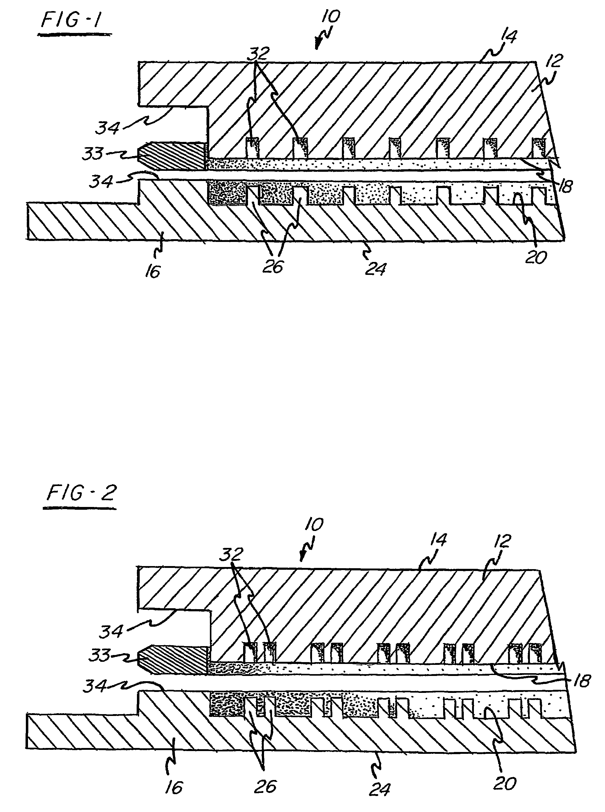
[0041]An unconventional sputter target assembly was bonded in accordance with the invention as shown in FIGS. 1 and 2. The target was composed of high purity Ti and the backing plate was composed of Cu-1% Cr. The thermal expansion coefficients of the target and backing plate respectively are about 8.9 and 17.6. The male projections were provided in the backing plate with each projection having a height of about 0.05″. An insert comprising Cu—Ni, preferably having 1–50% Ni, was positioned adjacent the peripheral boundary of the assembly. The annular zone around the peripheral boundary of the assembly was E-beam welded under vacuum. Then, the assembly was pressure consolidated at room temperature such that the overall thickness of the assembly decreased by about 0.1″.

[0042]Although the thermal expansion coefficients of the target and backing plate are dissimilar, the bonded assembly does not separate and / or bow during high power level sputtering conditions enabling this assembly to ut...

example 2

[0043]An unconventional sputter target assembly was bonded in accordance with the invention as shown in FIGS. 1 and 2. The target was composed of high purity Ti with the backing plate composed of Cu—Ni, preferably having 1–50% Ni. The male projections were provided in the backing plate with each projection having a height of about 0.1″. No insert was used. The annular zone around the peripheral boundary of the assembly was E-beam welded under vacuum. Then, the assembly was pressure consolidated at room temperature such that the overall thickness of the assembly decreased by about 0.1″.

[0044]The Cu—Ni backing plate has low electrical conductivity which decreases the eddy current and has higher heat conductivity then conventional backing plates used in high power applications wherein the target consists of Ti or Ti alloys. Although the thermal expansion coefficients are dissimilar, the bonded assembly, similar to example 1,does not separate and / or bow during high power level sputterin...

example 3

[0045]Another unconventional sputter target assembly that can be bonded in accordance with the invention, as shown in FIGS. 1 and 2, includes a target composed of high purity Co and a backing plate composed of Cu-1% Cr. Male projections are provided in the backing plate with each projection having a height of about 0.1″. An insert comprising NiV is positioned adjacent the peripheral boundary of the assembly. The annular zone around the peripheral boundary of the assembly is E-beam welded under vacuum. Then, the assembly is pressure consolidated at room temperature such that the overall thickness of the assembly decreases by about 0.1″.

[0046]Although the thermal expansion coefficients are different, the bonded assembly does not separate and / or bow during high power level sputtering conditions enabling this assembly to utilize a backing plate having higher thermal conductivity and lower electrical conductivity then conventional assemblies which use Co or Co alloy targets.


PUM

PropertyMeasurementUnit
Fractionaaaaaaaaaa
Temperatureaaaaaaaaaa
Pressureaaaaaaaaaa

Abstract

The present application pertains to unconventional sputter target/backing plate assemblies (10) for high power operation and to the low temperature method of making them. The sputter target/backing plate assemblies (10) comprise targets (12) and backing plates (16) having dissimilar thermal coefficients of expansion. Although the consolidated targets (12) and backing plates (16) have dissimilar thermal coefficients of expansion, they are able to be bonded together and used at high sputtering temperatures without bowing or bending and are able to utilize backing plates (16) normally associated with a specified target metal. In the method of making, a plurality of male projections (16) are formed in one member of the assembly (10) with a plurality of corresponding female grooves (32) formed in the other surface. The assembly (10) is bonded by conventional techniques around an annular zone that surrounds the male (26) and female portions (32). The assembly (10) is then pressure consolidated at low temperature so that the projections are force fit into the female recesses.

Description

CROSS-REFERENCE TO RELATED APPLICATIONS[0001]Priority filing benefit of (1) international PCT application PCT / US01 / 48480 filed Dec. 13, 2001, and published under PCT 21(2) in the English language; and (2) U.S. Provisional application Ser. No. 60 / 256,110 filed Dec. 15, 2000.FIELD OF THE INVENTION[0002]The present application pertains to sputter target / backing plate assemblies for high power operation and to the low temperature method of making them.BACKGROUND OF THE INVENTION[0003]Cathodic sputtering is widely used for the deposition of thin layers of material onto desired substrates. Basically, this process requires gas ion bombardment of a target having a face formed of a material that is to be deposited as a thin film or layer on a substrate. Ion bombardment of the target not only causes atoms or molecules of the target material to be sputtered, but imparts considerable thermal energy to the target. This heat is dissipated by use of a cooling fluid typically circulated beneath or ...

Claims


Application Information

Patent Timeline
IPC IPC(8): B23K31/02B23K20/12B23K9/00B23K9/025B23K15/00B23K15/04B23K15/06C23C14/34H01J37/34
CPCB23K9/0026B23K9/025B23K15/0006B23K15/04B23K15/06B23K20/12B23K20/129B23K31/02C23C14/3407H01J37/3435B23K15/00
Inventor IVANOV, EUGENE Y.CONARD, HARRY W.
Owner TOSOH SMD
Why Eureka
Try Eureka