LED driving semiconductor circuit and LED driving apparatus including the same

a technology of led driving and semiconductor circuits, which is applied in the direction of instruments, lighting support devices, pulse techniques, etc., can solve the problems of constant power loss increased power loss, and affecting the small size of led driving apparatus, so as to achieve the effect of reducing the power loss of the diod

Inactive Publication Date: 2006-10-03
COLLABO INNOVATIONS INC
View PDF8 Cites 39 Cited by
  • Summary
  • Abstract
  • Description
  • Claims
  • Application Information

AI Technical Summary

Benefits of technology

[0020]According to the present invention, a LED driving semiconductor circuit having high power-conversion efficiency can be realized. According to the present invention, a small-sized LED driving semiconductor circuit with a small number of parts can be realized. According to the present invention, a LED driving semiconductor circuit controls the current that flows through the light-emitting diode by the constant current even when the input voltage fluctuates.
[0049]According to the present invention, in the transient state in which the first switching device turns on from off, power loss in the diode can lower.

Problems solved by technology

However, there is a problem as is described below.
In this case, in such a direct current detection method as in the method using SD and LD, the power loss increases.
(3) Since the input voltage is detected using resistors, the power loss occurs constantly by these resistors for detecting input voltage while the LED driving apparatus is working.
(4) Number of circuit components increases, leaving hindrance to the small-sizing of the LED driving apparatus.
Particularly, in case of the bulb type LED lighting apparatus, it is unsuitable.

Method used


Image

  • LED driving semiconductor circuit and LED driving apparatus including the same
  • LED driving semiconductor circuit and LED driving apparatus including the same
  • LED driving semiconductor circuit and LED driving apparatus including the same

Examples


embodiment 1

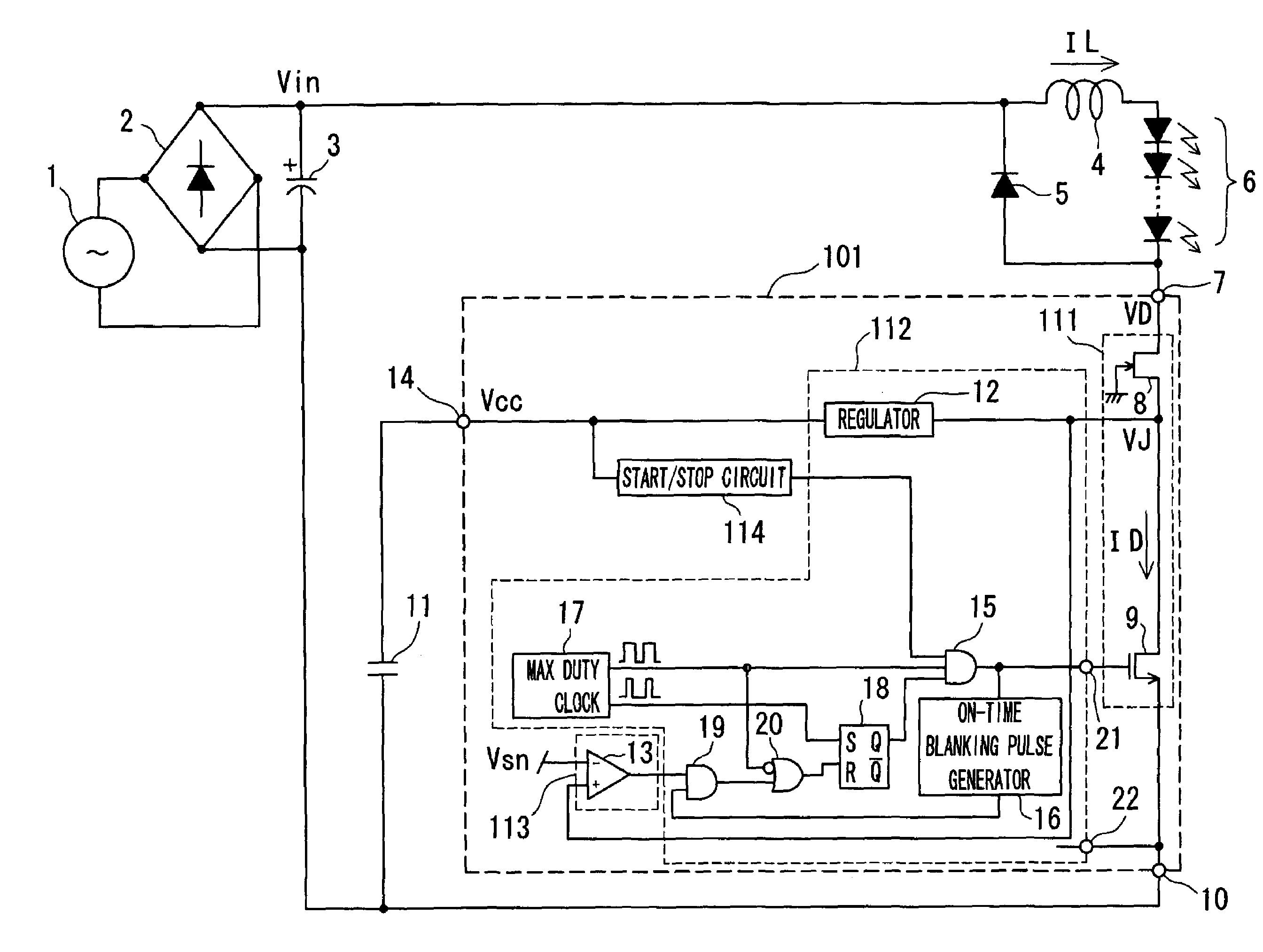
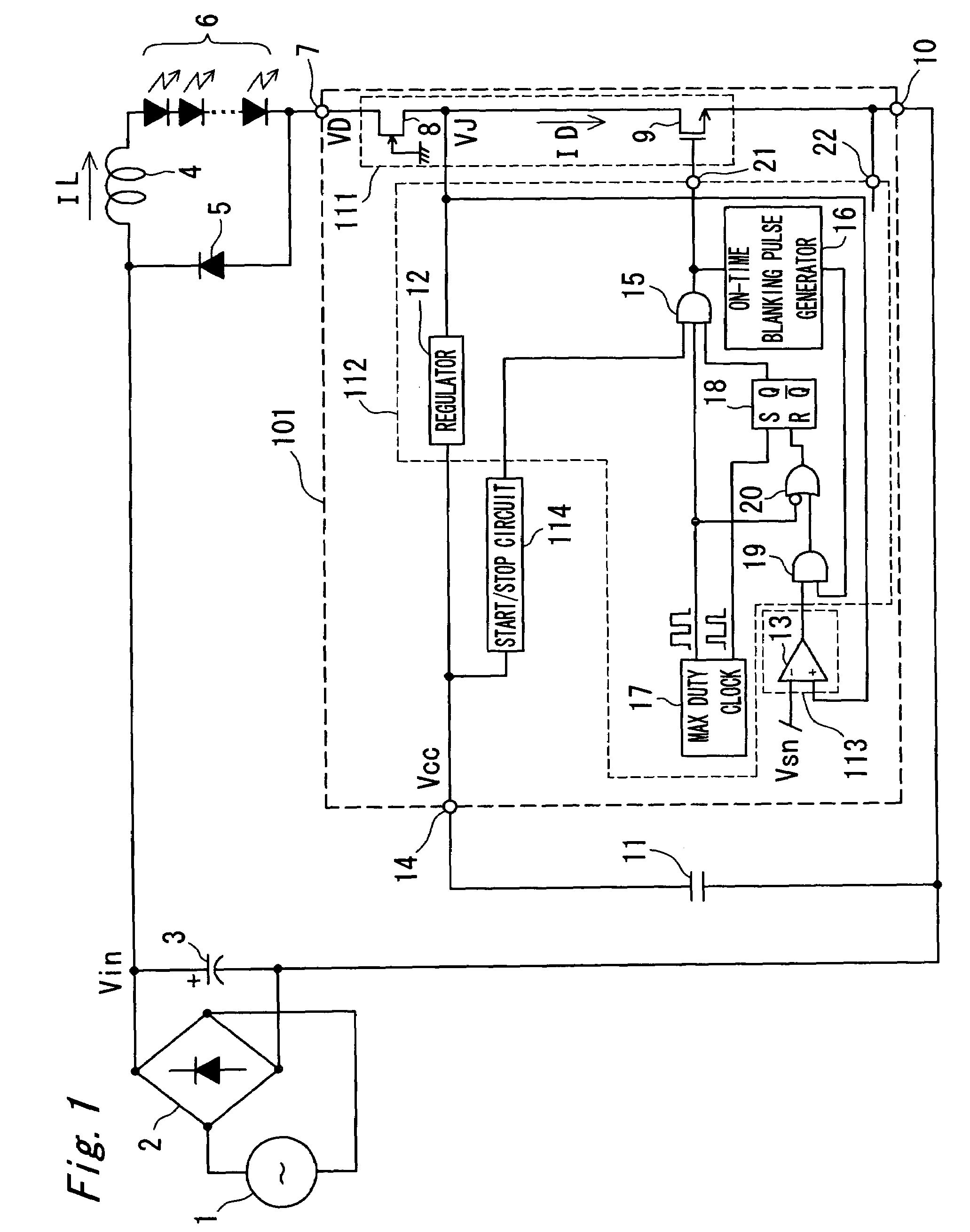
[0077]The LED driving apparatus of the present invention has a light-emitting diode block (which includes a choke coil 4, a diode 5, and a light-emitting diode 6), a LED driving semiconductor circuit 101 which controls the light-emitting diode block, and a capacitor 11 connected to the LED driving semiconductor circuit 101. In the LED driving apparatus of the present invention shown in FIG. 1, although a DC voltage Vin is inputted as the input voltage, it is also possible to input the output voltage of a DC source voltage in place of the AC power source 1.

[0078]In the LED driving apparatus of the embodiment 1 according to the present invention, one end of the choke coil 4 is connected to the high potential side of the smoothing capacitor 3 and a DC voltage Vin is applied to it. The other ends of the choke coil 4 are connected to an anode terminal of the light-emitting diode 6.

[0079]The light-emitting diode(s) 6 includes a light-emitting diode or a group of a plural number of light-e...

embodiment 2

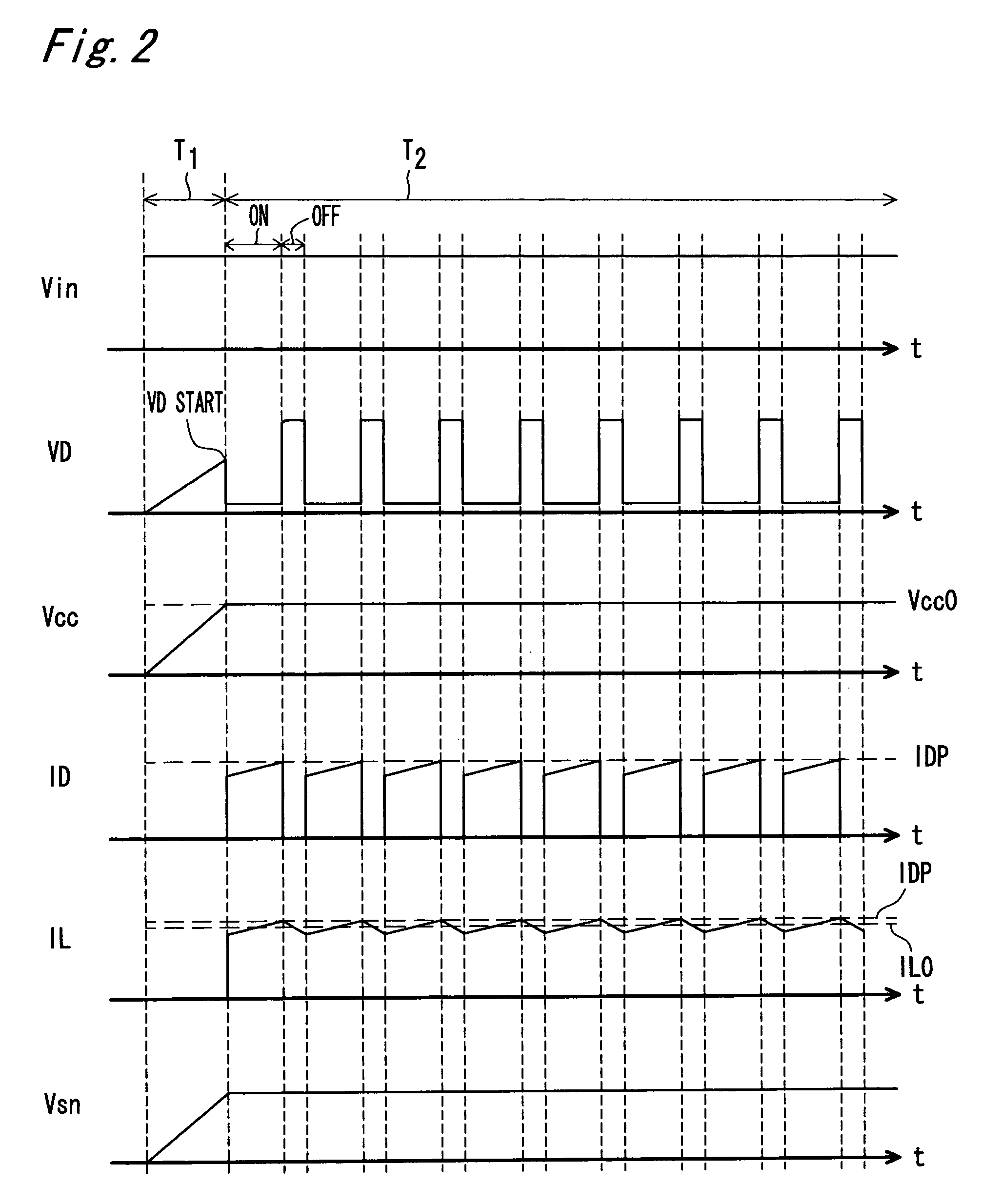
[0123]The detection reference voltage Vsn of the drain current detection circuit 113 of the embodiment 2 is variable with the voltage inputted to the external terminal SN 521. For example, as shown in FIG. 6, when gradually lowering the voltage Vsn to be inputted to the external terminal SN 521 in three steps, the level of the DRAIN current detected by the drain current detection circuit 113 also declines gradually in three steps, accordingly the current ID flowing through the switching device 9 declines gradually also in three steps. As a result, a current PWM controlled flows through the switching device 9 as shown by the ID of FIG. 6.

[0124]The current IL flowing through the choke coil 4 (that is, the current flowing through the light-emitting diode 6) becomes as shown in FIG. 6, hence the average current IL0 of the light-emitting diode 6 declines in three steps as shown in FIG. 6. As has been described, the average current of the light-emitting diode 6 changes based on the Vsn vo...

embodiment 3

[0131]FIG. 8 is a circuit diagram showing the LED driving apparatus when using a zener diode 822 as the clamp circuit 722. For example, a zener diode 822 is used for the clamp circuit 722 of the embodiment 3 as shown in FIG. 8. A cathode terminal of the zener diode 822 is connected to the DRAIN terminal 7 and an anode terminal is connected to the GND / SOURCE terminal 10.

[0132]The LED driving semiconductor circuit of the embodiment 3 of the present invention and the LED driving apparatus including the same further have the following effects in addition to the effects which were shown in the embodiments 1 and 2 of the present invention. In the LED driving apparatus of the embodiment 3 of the present invention, while the control circuit 112 controls ON / OFF of the switching device 9 intermittently, it is possible to clamp a jump of the voltage VD on the higher potential side of the switching device block 111 that is caused by the wiring capacitance and / or the wiring inductance to a volta...


PUM


Abstract

A LED driving semiconductor circuit of the present invention includes a first input terminal connected to a light-emitting diode, a switching device block having a first FET and a first switching device, a reference voltage terminal which is connected to the first FET and outputs the reference voltage, a start / stop circuit which outputs a start signal when the reference voltage is equal to or larger than a predetermined value and outputs a stop signal when the reference voltage is less than the predetermined value, a current detection circuit which detects the current flowing through the first switching device, and a control circuit which controls ON / OFF of the first switching device intermittently at the predetermined frequency based on the output signal of the start / stop circuit and the output signal of the current detection circuit so that the constant current flows through the light-emitting diode.

Description

BACKGROUND OF THE INVENTION[0001]1. Field of the Invention[0002]The present invention relates to a light-emitting diode (LED) driving semiconductor circuit and a light-emitting diode (LED) driving apparatus including the same. In particular, the present invention relates to a lighting apparatus using the light-emitting diode.[0003]2. Description of the Related Art[0004]In recent years, a LED driving semiconductor circuit and a LED driving apparatus including the same are developed and are put into practical use. A LED driving apparatus of a first prior art is disclosed in JP 2001-313423, (A patent document 1).[0005]In the LED driving apparatus of the first prior art, a voltage boost chopper BUT includes an inductor L, a diode D (a light-emitting diode LED can also serve as the diode D) which is connected to the inductor L in series, and a switching element Q of which one end is connected to a connecting point between the inductor L and the anode of the diode D (in the explanation of...

Claims


Application Information

Patent Timeline
Patent Type & Authority Patents(United States)
IPC IPC(8): H01L31/14G09G3/06H05B37/02H05B44/00H01L33/00
CPCH05B33/0815Y02B20/347Y02B20/30H05B45/375
Inventor HACHIYA, YOSHIAKIARAKAWA, RYUTARO
Owner COLLABO INNOVATIONS INC
Why Eureka
Try Eureka