

Raman amplification using a microstructured fiber
a microstructured fiber and amplifier technology, applied in the field of fiber raman amplifiers using microstructured fibers, can solve the problems of not being able to consider the merit of air-silica microstructured fibers given above, being quite unpractical for a real installation in a telecommunications system, and being rather complicated in the manufacturing of air-silica microstructured fibers with a very low attenuation. , to achieve the effect of enhancing the raman
- Summary
- Abstract
- Description
- Claims
- Application Information
AI Technical Summary
Benefits of technology
Problems solved by technology
Method used
Image

Examples
example 1
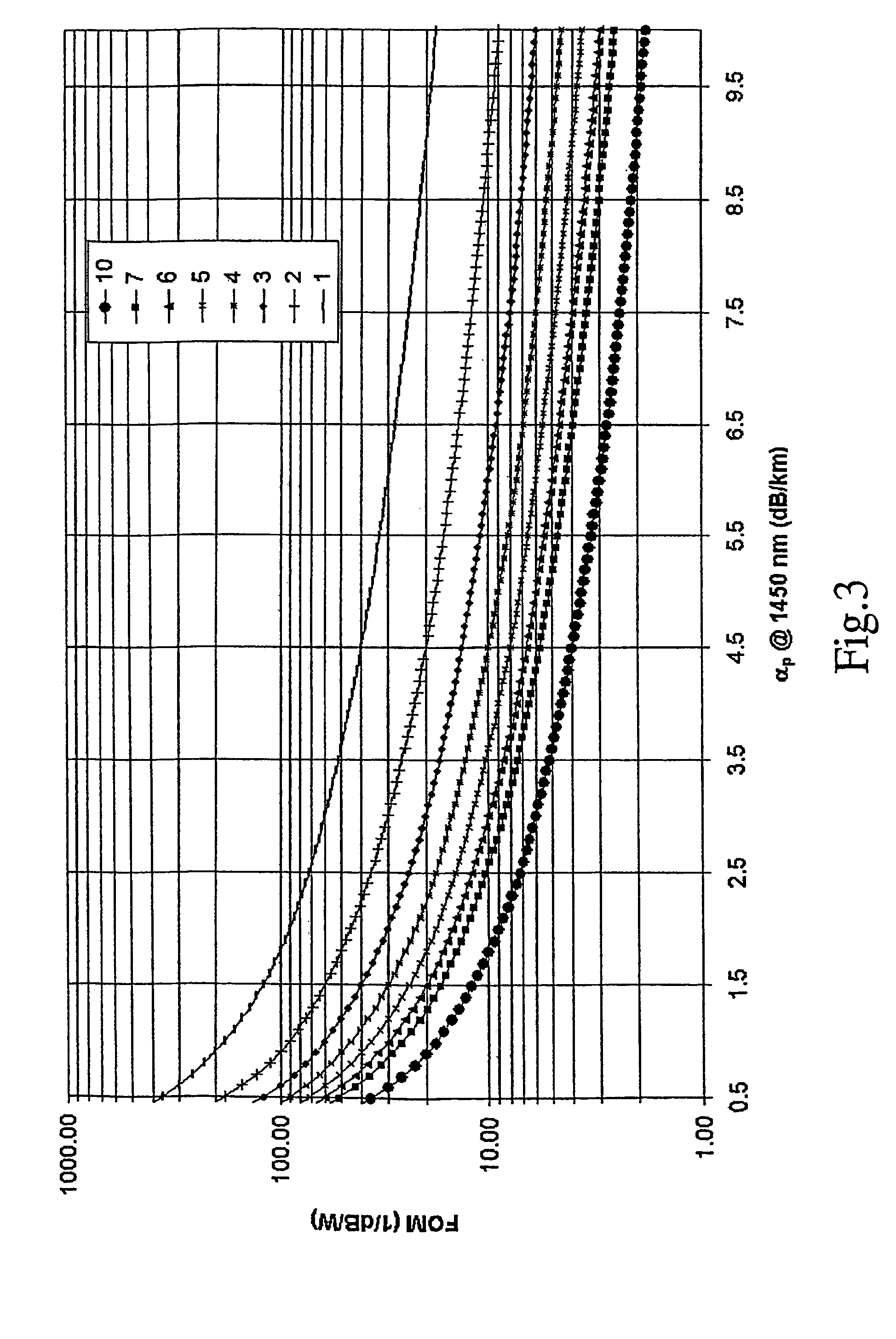
[0088]FIG. 3 shows several curves representing the figure of merit for Raman amplification according to formula [1] versus the attenuation at the pump wavelength for a microstructured fiber having a silica core doped with 20% mol of germania. In order to plot the curves, a value of gR at 1550 nm of 18·10−14 m / W has been assumed for the microstructured fiber. Different curves correspond to different values of effective area of the fiber, according to the legend added in FIG. 3.
[0089]As it can be seen, values of figure of merit of about 10 1 / dB / W can be obtained with relatively high values of both attenuation (3–4 dB / km) and effective area (4–6 μm2). This is advantageous, as a relatively high value of attenuation allows to use an easier manufacturing process, while a relatively high value of effective area facilitates coupling.
[0090]With lower values of attenuation and / or effective area, exceptionally high values of figure of merit may be obtained (>15 1 / dB / W). This is important mainl...
example 2
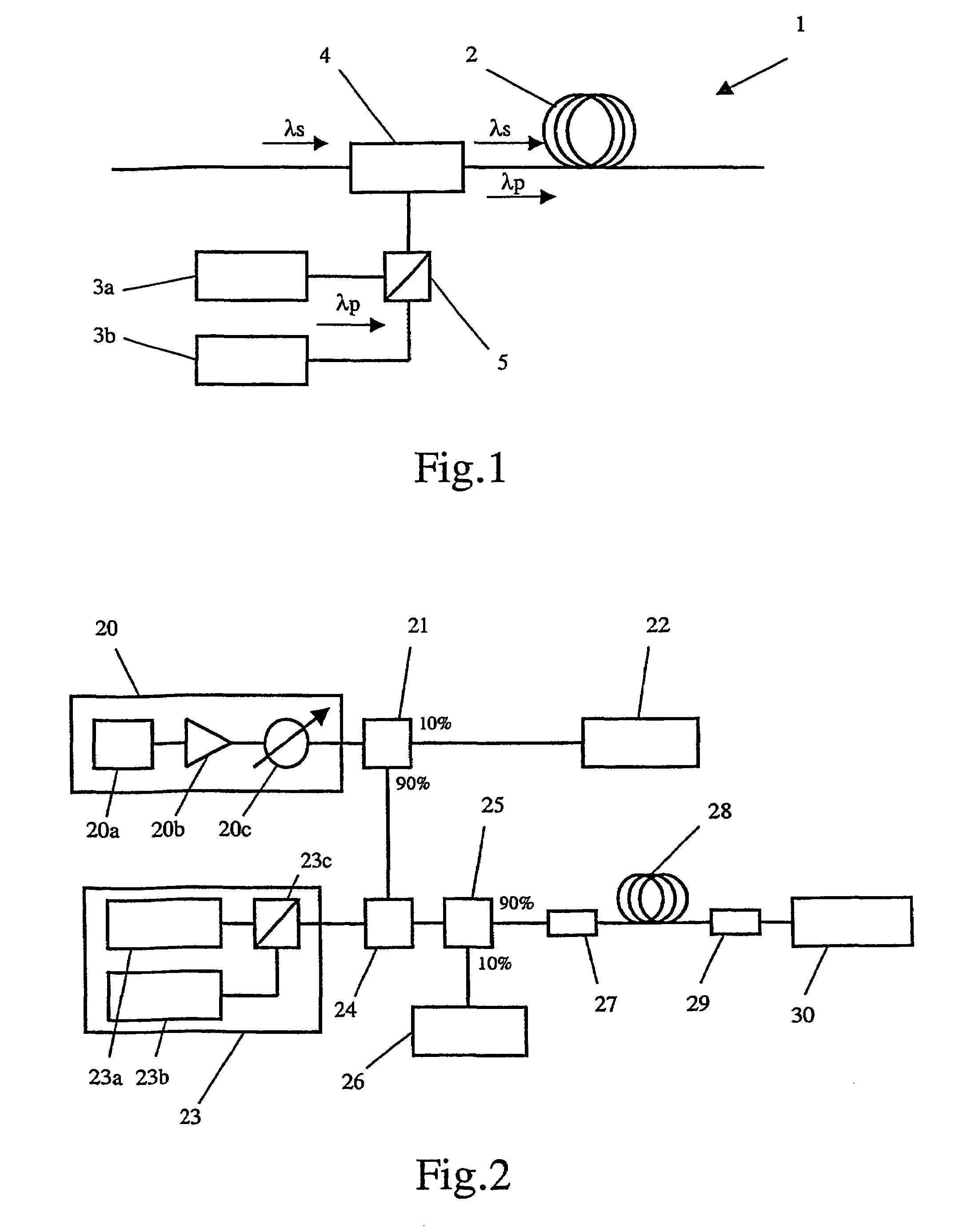
[0091]The Applicant has made a series of simulations for a configuration of a Raman amplifier according to FIG. 1. A signal having a wavelength of 1550 nm and a pump radiation having a wavelength of 1450 nm were considered. The power emitted by each pump laser was supposed to be 200 mW. FIG. 4 shows three curves representing the on-off gain that can be obtained by using for the Raman amplifier a microstructured fiber according to the invention (curve 40a), a microstructured fiber having a pure silica core (curve 40b) and a High Non-Linear Fiber according to the article of Tsuzaki et al. (curve 40c), versus the length of the fiber. The on-off gain was calculated by using formulae [4], [5]. A value of 18·10−14 m / W at 1550 nm of the Raman gain coefficient, an effective area of 5 μm2 and an attenuation at the pump wavelength of 1450 nm of 4 dB / km have been assumed for plotting the curve 40a. A value of 7.74·10−14 m / W at 1550 nm of the Raman gain coefficient, an effective area of 5 μm2 a...
example 3
[0092]FIG. 5 shows a series of level curves of the Raman gain peak that can be reached by a microstructured fiber according to the invention. The Raman gain peak was evaluated as G=Gon-offe−αL, wherein Gon-off was calculated by using the formula [4], α is the attenuation of the fiber at the signal wavelength and L is the length of the fiber. In order to plot the level curves of FIG. 5 the maximum value of G versus the length L was considered. An effective area of 5 μm2, an attenuation at the pump wavelength of 4.0 dB / km and an attenuation at the signal wavelength of 4.0 dB / km have been assumed. The level curves are shown in a plot having in the x-axis the pump power for each laser source, in a configuration of Raman amplifier having two pump lasers coupled through a polarization beam splitter, and in the y-axis the germania concentration. The Raman gain coefficient gR has been evaluated for each germania concentration according to formula [3]. The value of the calculated Raman gain ...
PUM
 Abstract
Description
Claims
Application Information