
Flanged coupling device with a static ball-and-socket joint

a static ball-and-socket joint and coupling device technology, which is applied in the direction of hose connections, couplings, mechanical equipment, etc., can solve the problems of insufficient reliability of sealing provided by single-barrier gaskets, damage to gaskets, and gaskets to be destroyed

Inactive Publication Date: 2006-10-10
SN DETUDE & DE CONSTR DE MOTEURS DAVIATION S N E C M A +1
View PDF4 Cites 6 Cited by
  • Summary
  • Abstract
  • Description
  • Claims
  • Application Information

AI Technical Summary

Benefits of technology

The solution enables increased angular deflection between flowline axes, reduces radial loads, and provides reliable sealing at high temperatures and pressures, extending the coupling's lifetime and suitability for hydrogen-containing fluids.

Problems solved by technology

A coupling of that type is generally used with low pressure flowlines and it does not lend itself to high pressures which generate significant radial forces causing the gasket to be destroyed.
A coupling of that type suffers from the drawback of having a female coupling member with an inner sealing surface presenting a slope of less than 20°, giving rise to intense radial compression that can damage the gasket.
Experience shows that the sealing provided by a single-barrier gasket is not sufficiently reliable in situations where the values of pressure and temperature parameters are high, particularly with fluids that are characterized by high penetrability.
Nevertheless, the above-mentioned gaskets do not provide sealing with fluids that are characterized by operating parameters involving high penetrability at high temperature that can be as much as 800° C. and at a pressure greater than 4500 Newtons per square centimeter (N / cm2).
In that device, the angle between the axes of the flowlines is very limited, thus restricting its field of application.
By failing to limit the magnitude of the radial forces, the lifetime of a coupling subject to high pressure and high cyclic loading will be short.

Method used


Image

  • Flanged coupling device with a static ball-and-socket joint
  • Flanged coupling device with a static ball-and-socket joint
  • Flanged coupling device with a static ball-and-socket joint

Examples


Embodiment Construction

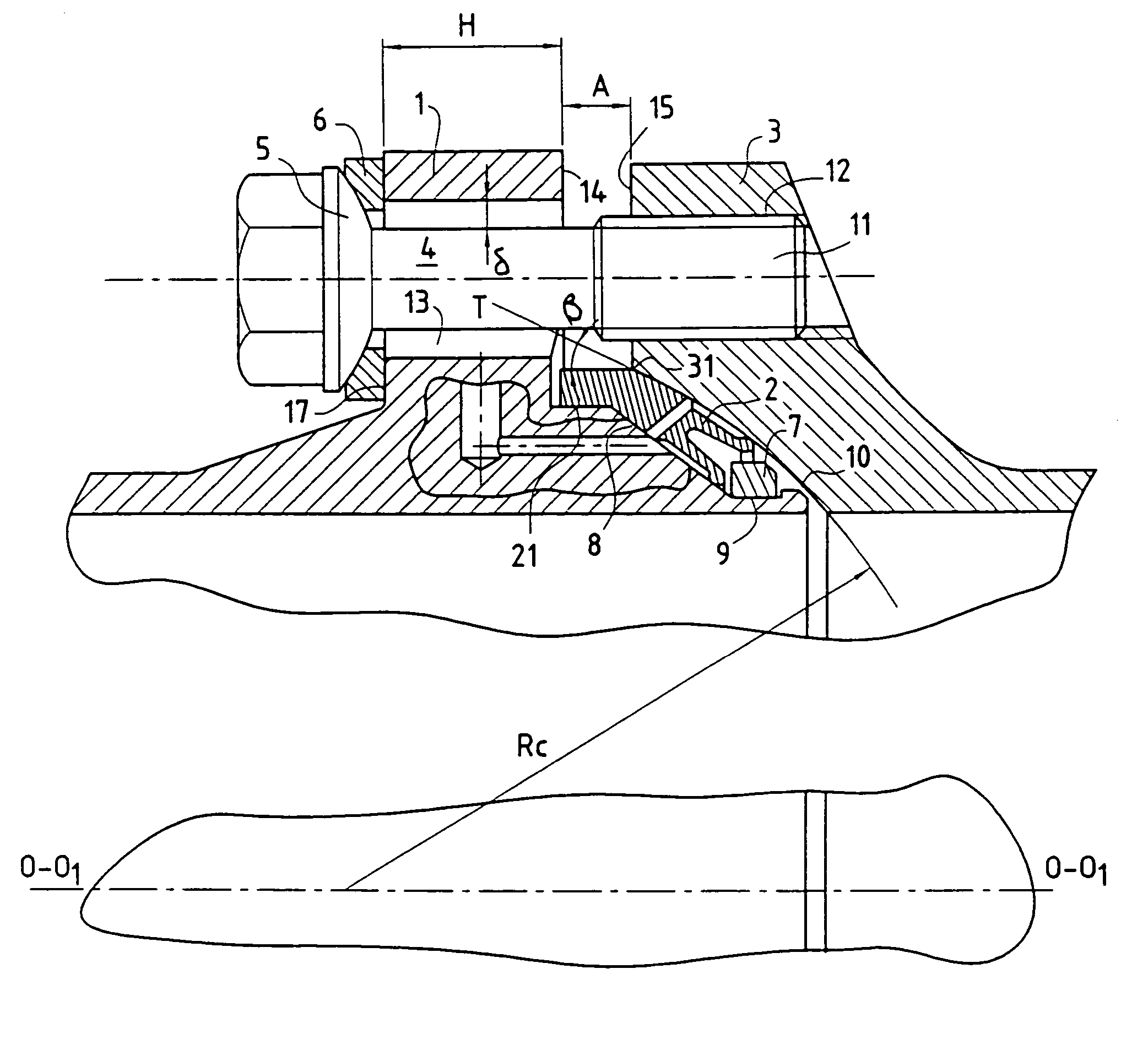
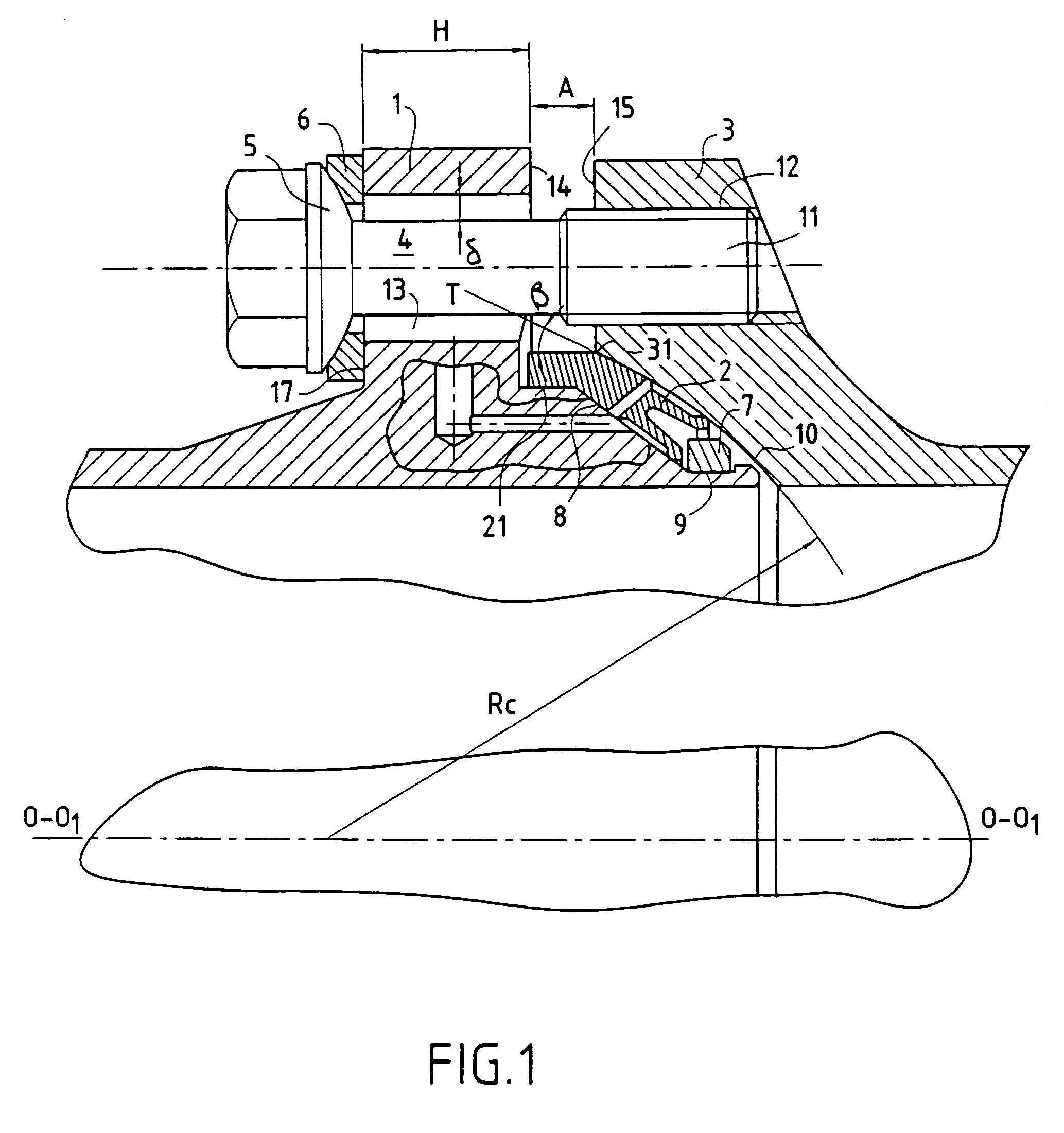
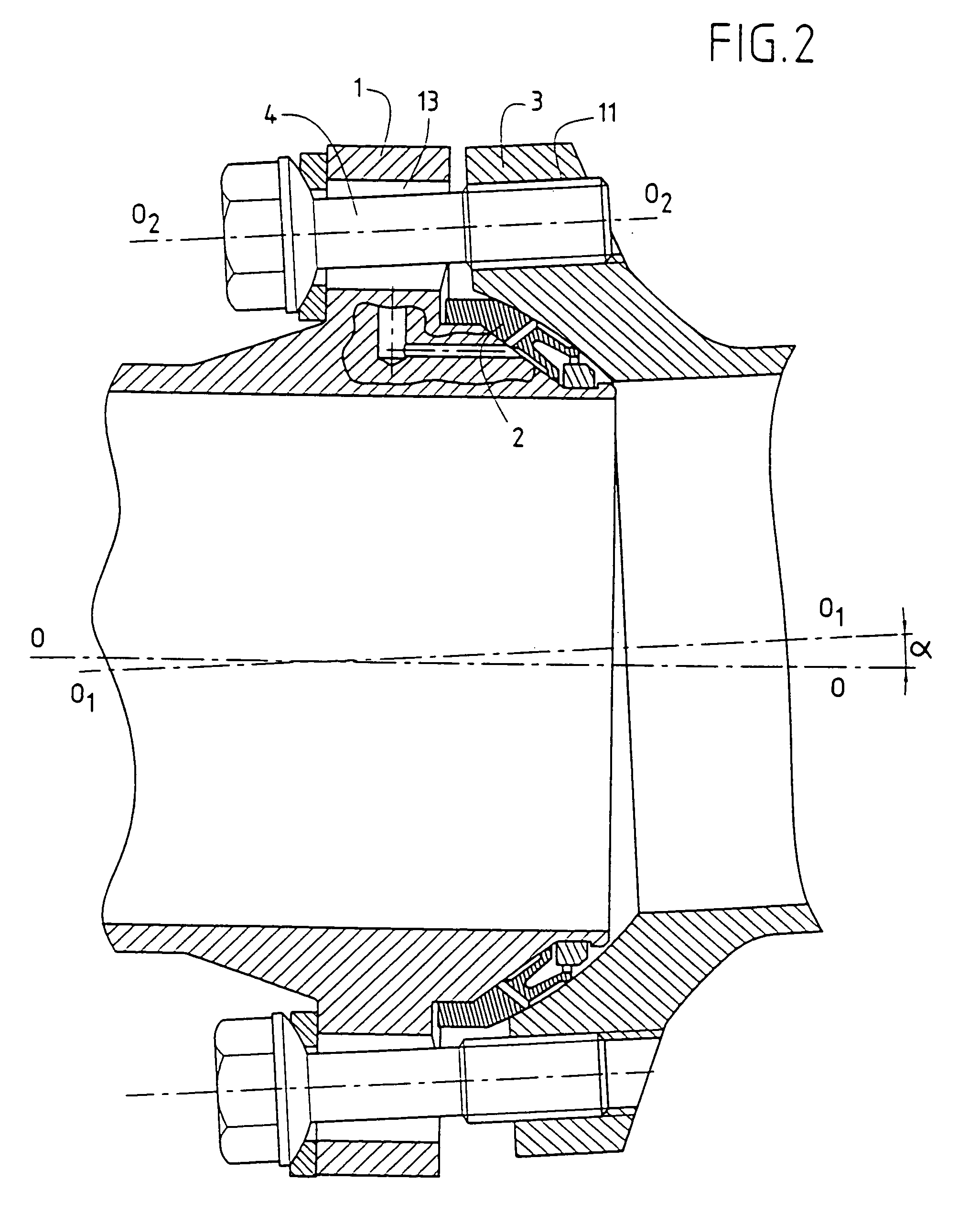
[0064]Reference is now made to the drawings and more precisely to FIG. 1 which shows a flanged coupling device with a static ball-and-socket joint. The device comprises a first coupling member 1, a two-barrier metal gasket 2, a second coupling member 3, bolts 4 with spherical heads 5, washers 6 with spherical bearing surfaces, and a retaining ring 7. The first coupling member 1 has a seat 21 with a cylindrical surface, a sealing surface 8 of conical shape (which in a variant could be of spherical, toroidal, or other shape), and a channel 9 for receiving the retaining ring 7 which is split into a plurality of portions. The second coupling member 3 has a concave sealing surface 10 forming a portion of a sphere with a radius of curvature Rc centered on the flow axis. The radius of curvature Rc of the spherical surface 10 from a center situated on the central axis O1—O1 of the second coupling member 3 is selected in such a manner that the tangent T to the outer spherical surface 10 at t...


PUM


Abstract

The invention relates to couplings for fluid flowlines and more particularly to couplings that can be dismantled comprising flanges and a static ball-and-socket joint for use with flowlines having a diameter lying in the range 40 mm to 200 mm and transporting fluids (gases or liquids) of high penetrability, at high temperature of up to 800° C., and at high pressure of up to 450×105 Pa. Teh device comprises a flanged coupling device with a static ball-and socket joint comprising a first coupling member (1) having a conical sealing surface (8), a second coupling member (3) having concave sealing surface (10) of spherical shape, a two-barrier metal gasket (2) disposed between the sealing surface (8, 10) of the first and second coupling members (1, 3), and assembly means (4) for assembling the first and second coupling members (1, 3) together so as to hold the gasket (2) between their respective sealing surfaces (8, 10). The metal gasket (2) is made of a refractory granular nickel alloy that withstands hydrogen, having uniform fine grain structure with isotropic properties and coated in three sealing layers, the first layer (27) being of nickel, the second layers (28) being of silver, and the third layer (29) being an antifriction lubricant of an inorganic material that is compatible with the fluid used.

Description

[0001]This application is a 371 national phase filing of PCT / EP01 / 07851 filed Jun. 29, 2001.FIELD OF THE INVENTION[0002]The present invention relates to couplings for fluid flowlines and more particularly to separable flanged couplings with a static ball-and-socket joint for flowlines of diameter lying in the range 40 millimeters (mm) to 200 mm transporting fluids (gases or liquids) of high penetrability, at high temperature possibly reaching 800° C., and at a pressure possibly as high as 450×105 Pascals (Pa.).PRIOR ART[0003]Flanged coupling devices with static ball-and-socket joints are provided to allow the axes of the flowlines to be at a certain angle relative to each other so as to prevent stresses building up on the coupling members and also on the pipework in order to provide adequate lifetime and to allow for multiple overhauls.[0004]The angle between the axes of the flowlines can be accommodated in two ways:[0005]in a first system, an end piece having a male spherical beari...

Claims


Application Information

Patent Timeline
Patent Type & Authority Patents(United States)
IPC IPC(8): F16L19/00F16L27/053F16L27/06
CPCF16L27/053F16L27/06Y10T403/32631Y10S285/917
Inventor KATORGIN, BORIS IVANOVITCHTCHVANOV, VLADIMIR KONSTANTINOVITCHGROMYKO, BORIS MIKHAILOVITCHMATVEEV, EYGUENI MIKHAILOVITCHMIKHALIOV, IGOR ALEXANDROVITCHMITIOUKOV, YOURI VASSILIEVITCHPOSTNIKIOV, IVAN DENISSOVITCHJELEZNIAK, OLGA NIKOLAEVNA
Owner SN DETUDE & DE CONSTR DE MOTEURS DAVIATION S N E C M A
Learn More