Multipurpose adiabatic potable water production apparatus and method

a technology of adiabatic adiabatic and production apparatus, which is applied in the direction of defrosting, cooling apparatus, separation process, etc., can solve the problems of significant drop in relative humidity and higher efficiency, and achieve the effect of safe drinking and reducing energy costs

Active Publication Date: 2006-10-17
SKYWATER INT LLC
View PDF15 Cites 26 Cited by
  • Summary
  • Abstract
  • Description
  • Claims
  • Application Information

AI Technical Summary

Benefits of technology

[0004]It is an object of the present invention to provide novel means and methods for condensing and collecting water for drinking purposes from the atmosphere. It is a further object of the invention to provide means to purify water not yet fit for human consumption, thereby rendering the water safe to drink. It is yet a further object of the present invention to provide means and methods to distill ordinary water at relatively low ambient temperatures, thereby substantially reducing the energy costs normally associated with this task. These and other objects are fulfilled by employing sophisticated refrigeration techniques including multiple evaporators, adiabatic cooling techniques, reheat, as well as a novel defrost mechanism, all operating within an enclosed ducted air passageway. These techniques allow the apparatus to capture relatively large quantities of water, up to the greatest quantity of moisture per unit volume of air possible under a variety of conditions and situations. Upon determining whether the apparatus is to function as a simple air to water conversion device, a water distillation device, or desalination device, controls relevant to each separate operation may be activated in accordance with the present invention.

Problems solved by technology

The air stream is then passed across an air stream heating element where the temperature of the air is drastically increased, simultaneously resulting in a significant drop in relative humidity.
Further, the task is accomplished with a significant decrease in energy usage, thereby resulting in higher efficiencies.

Method used


Image

  • Multipurpose adiabatic potable water production apparatus and method
  • Multipurpose adiabatic potable water production apparatus and method
  • Multipurpose adiabatic potable water production apparatus and method

Examples


Embodiment Construction

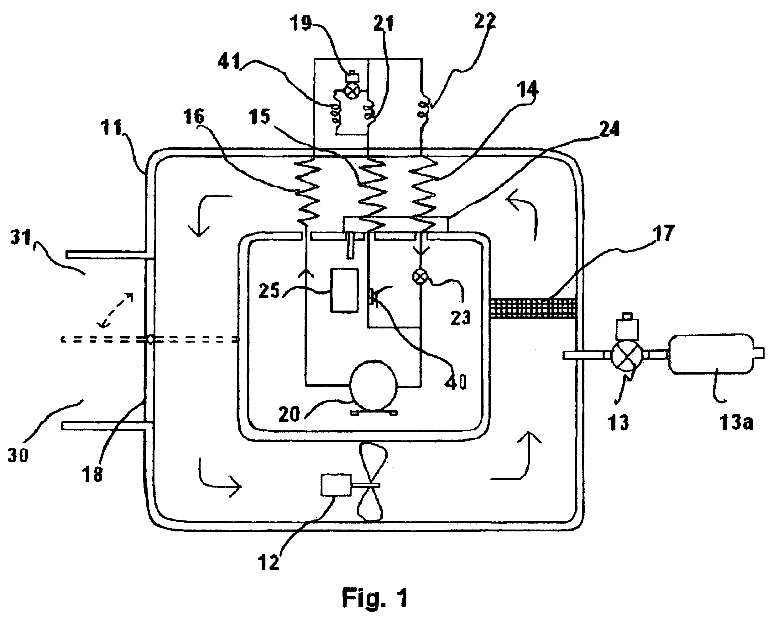
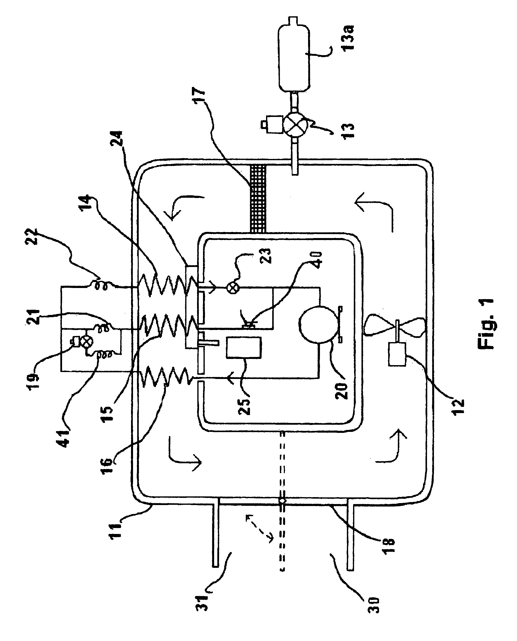
[0013]Referring to FIG. 1, major components of the invention are positioned within a fully enclosed loop air passage duct 11. In a preferred embodiment, duct 11 is insulated from ambient atmospheric conditions. A continuous flow of air containing water vapor (humidity), or into which moisture is injected (see below), is circulated through the closed loop air passage duct 11 by air movement means 12 such as a motor driven fan in, for example, a counterclockwise direction. A sequence of refrigeration components 14, 15, 16 is positioned within the duct 11 in ascending numerical order downstream from fan 12. These refrigeration components comprise a first air stream cooling element 14 such as a first refrigerant evaporator having an exterior surface, a second air stream cooling element 15 such as a second refrigerant evaporator having an exterior surface, and an air stream heating element 16, which in the preferred embodiment is a condenser of the refrigeration system. The refrigeration...


PUM

PropertyMeasurementUnit
humidityaaaaaaaaaa
temperatureaaaaaaaaaa

Abstract

Apparatus and methods for transforming water vapor into potable water by using a vapor compression refrigeration system which includes first and second cooling elements disposed in a closed loop air passage duct that provides a continuous air circulation pattern driven by a fan or similar device. Water is introduced into the circulating air and undergoes adiabatic cooling followed by two stage cooling, first at a temperature below the dew point and then at a lower temperature at or below freezing. Water is collected from the air in each step and the air is thereafter heated back up by the condensing element of the refrigeration system enabling it to absorb more water vapor at the point of introduction. The air is recirculated and processed as above to permit cyclical water recovery.

Description

BACKGROUND OF THE INVENTION[0001]The present invention relates to an improved apparatus for transforming atmospheric water vapor, or non-potable water vapor vaporized into air, into potable water, and particularly for obtaining drinking quality water through the formation of condensed water vapor upon one or more surfaces which are maintained at a temperature at or below the dew point for a given ambient condition. The surfaces upon which the water vapor is condensed are kept below the dew point by means of a refrigerant medium circulating through a closed fluid path, which includes refrigerant evaporation apparatus, thereby providing cooling of a bypassing airstream, and refrigerant condensing apparatus for providing heat to the airstream.[0002]U.S. Pat. No. 5,301,516—Poindexter and U.S. Pat. Nos. 5,106,512 and 5,149,446—Reidy each disclose potable water collection apparatus comprising refrigeration apparatus to maintain a cooling coil at a temperature below the dew point to cause ...

Claims


Application Information

Patent Timeline
Patent Type & Authority Patents(United States)
IPC IPC(8): F25D17/06B01D21/30C02F1/12F25B5/02F25B40/04F25B41/04F25D3/02F25D21/00F25D21/14
CPCB01D5/0006B01D5/0039B01D5/009B01D5/0093C02F1/12F25B5/02F25B40/04F25B41/043C02F2103/08F25B2339/047F25B2700/21151F25B41/22Y02A20/00Y02A20/124
Inventor MERRITT, THOMAS D.
Owner SKYWATER INT LLC
Why Eureka
Try Eureka