Control apparatus for an internal combustion engine

a control apparatus and internal combustion engine technology, applied in mechanical devices, electric control, machines/engines, etc., can solve problems such as engine misfire and engine misfir

Inactive Publication Date: 2006-10-17
HONDA MOTOR CO LTD
View PDF3 Cites 26 Cited by
  • Summary
  • Abstract
  • Description
  • Claims
  • Application Information

AI Technical Summary

Benefits of technology

[0011]As the temperature within the combustion chamber is lower, duration time of the spark ignition combustion needs to be longer so as to warm up the combustion chamber. According to one embodiment of the present invention, the above predetermined time period is set so that the predetermined time period is longer as the temperature within the combustion chamber immediately before the fuel cut is performed is lower. Thus, the compression ignition combustion can be performed without causing engine misfire.
[0012]As duration time of the fuel cut is longer, the temperature within the combustion chamber is lower. According to one embodiment of the present invention, the above predetermined time period is set in accordance with duration time of the fuel cut. Thus, the compression ignition combustion can be performed without causing engine misfire.

Problems solved by technology

If the temperature within the combustion chamber is lower than the predetermined temperature, engine misfire may occur even when the piston reaches the top dead center (TDC).
Even if operating conditions of the engine are within a range where the compression ignition combustion is allowed, engine misfire may occur because the temperature within the combustion chamber is low.

Method used


Image

  • Control apparatus for an internal combustion engine
  • Control apparatus for an internal combustion engine
  • Control apparatus for an internal combustion engine

Examples


Embodiment Construction

[0020]Preferred embodiments of the present invention will be now described referring to the accompanying drawings.

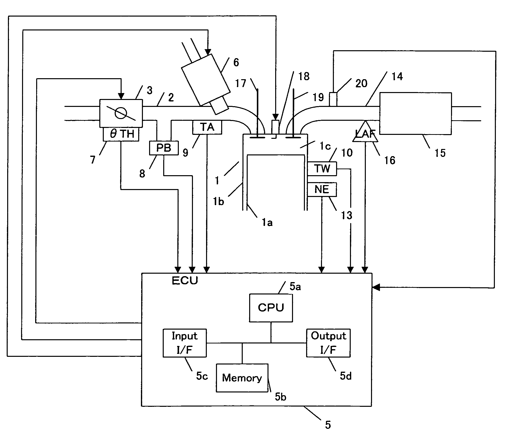
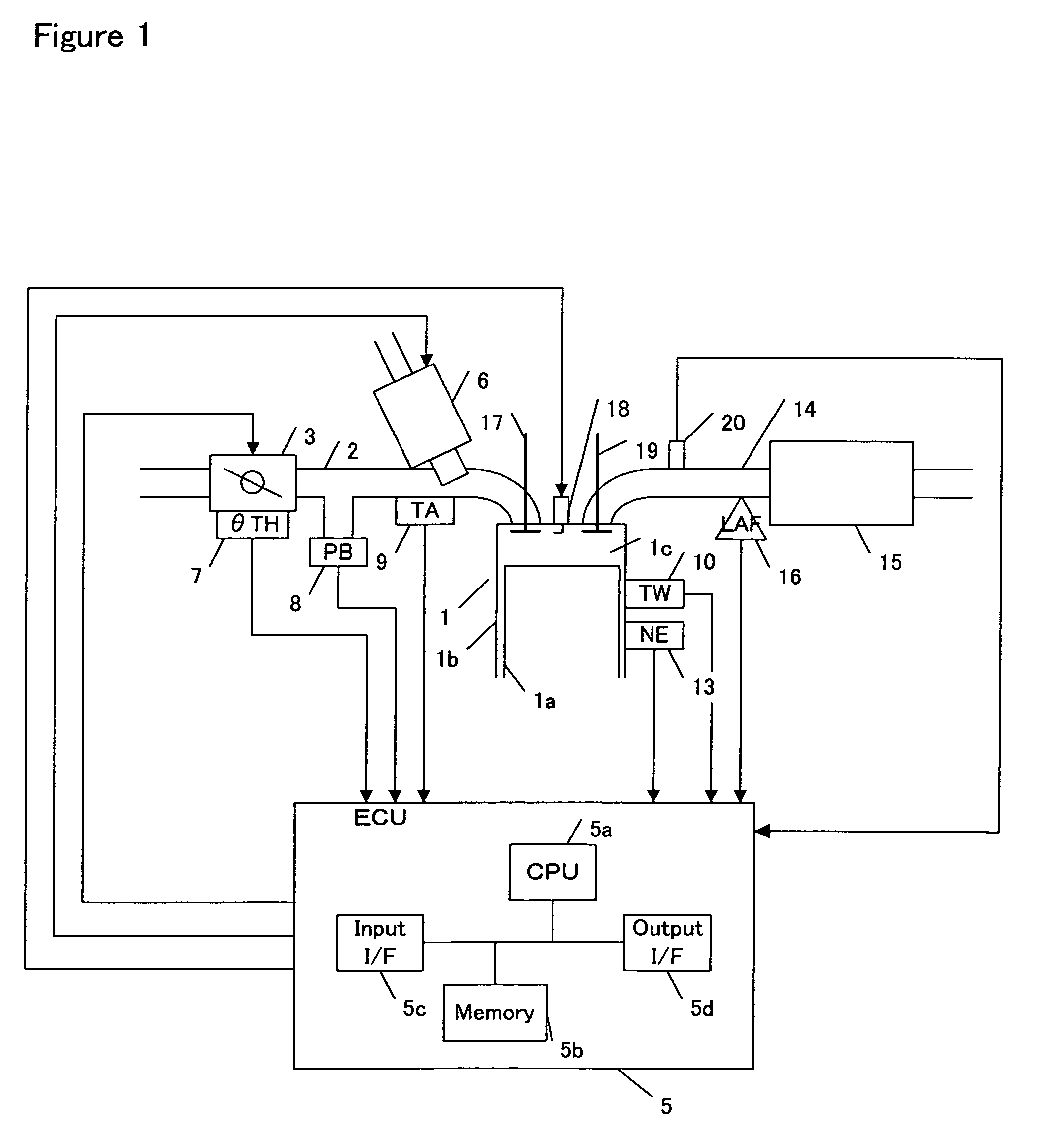
[0021]FIG. 1 is a block diagram of an internal combustion engine in accordance with one embodiment of the present invention. An internal combustion engine (hereinafter referred to as an “engine”) 1 is an inline four-cylinder engine, among which one cylinder is shown in FIG. 1. The engine is capable of switching between homogeneous charge compression ignition combustion (hereinafter referred to as “HCCI combustion”) and spark ignition combustion (hereinafter referred to as “SI combustion”). The engine 1 comprises a piston 1a and a cylinder 1b. A combustion chamber 1c is formed between the piston and the head of the cylinder. A spark plug 18 is attached in the combustion chamber 1c. The spark plug 18 is ignited in accordance with a signal from an electronic control unit (hereinafter referred to as an “ECU”) 5 when the SI combustion is performed. The structure of the ECU 5 ...


PUM


Abstract

A control apparatus for an internal combustion engine that is capable of switching between compression ignition combustion and spark ignition combustion is provided. The control apparatus is configured to perform fuel cut. The spark ignition combustion is performed over a time period after the fuel cut. The compression ignition combustion is permitted when the time period elapses. Fuel cut decreases the temperature within the combustion chamber. According to the invention, if fuel cut is performed, the temperature within the combustion chamber is raised by the spark ignition combustion. Since the compression ignition combustion is permitted after the temperature within the combustion chamber rises, engine misfire and an increase of NOx emission are prevented. The time period is preferably determined based on the temperature within the combustion chamber immediately before the fuel cut is performed.

Description

BACKGROUND OF THE INVENTION[0001]The present invention relates to an internal combustion engine capable of switching between spark ignition combustion and compression ignition combustion, and in particular relates to control for such an internal combustion engine after fuel-cut.[0002]A compression ignition type of internal combustion engine has advantage that fuel efficiency is high because high compression ratio is achieved. Such an engine has further advantage that the amount of NOx emission is low because the combustion temperature is low.[0003]In order to cause the compression self-ignition, the temperature of gas within a combustion chamber needs to be raised beyond a predetermined temperature. Heating of intake air or internal EGR is typically performed so as to raise the temperature within the combustion chamber.[0004]The temperature within the combustion chamber may not reach the predetermined temperature, for example, when the engine load is low. If the temperature within t...

Claims


Application Information

Patent Timeline
Patent Type & Authority Patents(United States)
IPC IPC(8): F02B3/00F02B1/12F02B11/00F02D41/12F02D41/30F02D43/00F02D45/00
CPCF02B1/12F02B11/00F02D41/126F02D41/3035F02D41/3076F02D41/1456F02D2200/0404F02D2200/0406F02D2200/0414
Inventor KITAMURA, TOHRUYAMAKI, TOSHIHIROKIMURA, TOMIOOKAZAKI, SHOHEIOKUBO, KATSURAKATO, AKIRA
Owner HONDA MOTOR CO LTD
Why Eureka
Try Eureka