Delivery mechanism for implantable stent

a delivery mechanism and stent technology, applied in the field of implantable medical devices, can solve the problems of reducing or complete loss of functional attributes, awkward operation, difficult to maintain steady, etc., and achieve the effects of convenient and precise stent positioning, convenient operation, and smooth retracting

Inactive Publication Date: 2006-10-17
BARD PERIPHERAL VASCULAR
View PDF191 Cites 162 Cited by
  • Summary
  • Abstract
  • Description
  • Claims
  • Application Information

AI Technical Summary

Benefits of technology

[0006]The present invention is directed to a stent delivery mechanism which is both easy to operate and facilitates extremely precise stent positioning. Several different configurations are described. For example, in a first embodiment, a simple V-shaped grip aligned generally longitudinally with the catheter to be deployed is utilized. A mechanical advantage gear mechanism is employed, which operates in conjunction with a ratchet to smoothly retract a sheath hub to which the outer sheath of the catheter is attached. The mechanism is easy to grasp and actuate in any rotational configuration. The V-shaped mechanism includes a body which contains the ratchet and a drive gear lever handle. The lever handle interacts with a drive pinion to drive the ratchet by a predetermined amount, thus retracting the sheath hub by a corresponding amount. The drive gear lever handle mechanism provides both the mechanical advantage, which results in movement of the outer sheath by a relatively small amount for a large displacement of the lever handle, and a much smoother operation than the direct ratchet operation of the prior art device.
[0007]In a second embodiment of the invention employs a hydraulic mechanism to both provide the mechanical advantage and achieve extremely smooth retraction operation. In addition, the use of hydraulics, as op

Problems solved by technology

Various diseases of blood vessels or hollow organs cause a stenosis or complete occlusion of their lumen, which results in a decrease or complete loss of their functional attributes.
This

Method used


Image

  • Delivery mechanism for implantable stent
  • Delivery mechanism for implantable stent
  • Delivery mechanism for implantable stent

Examples


first embodiment

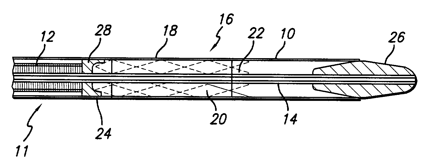
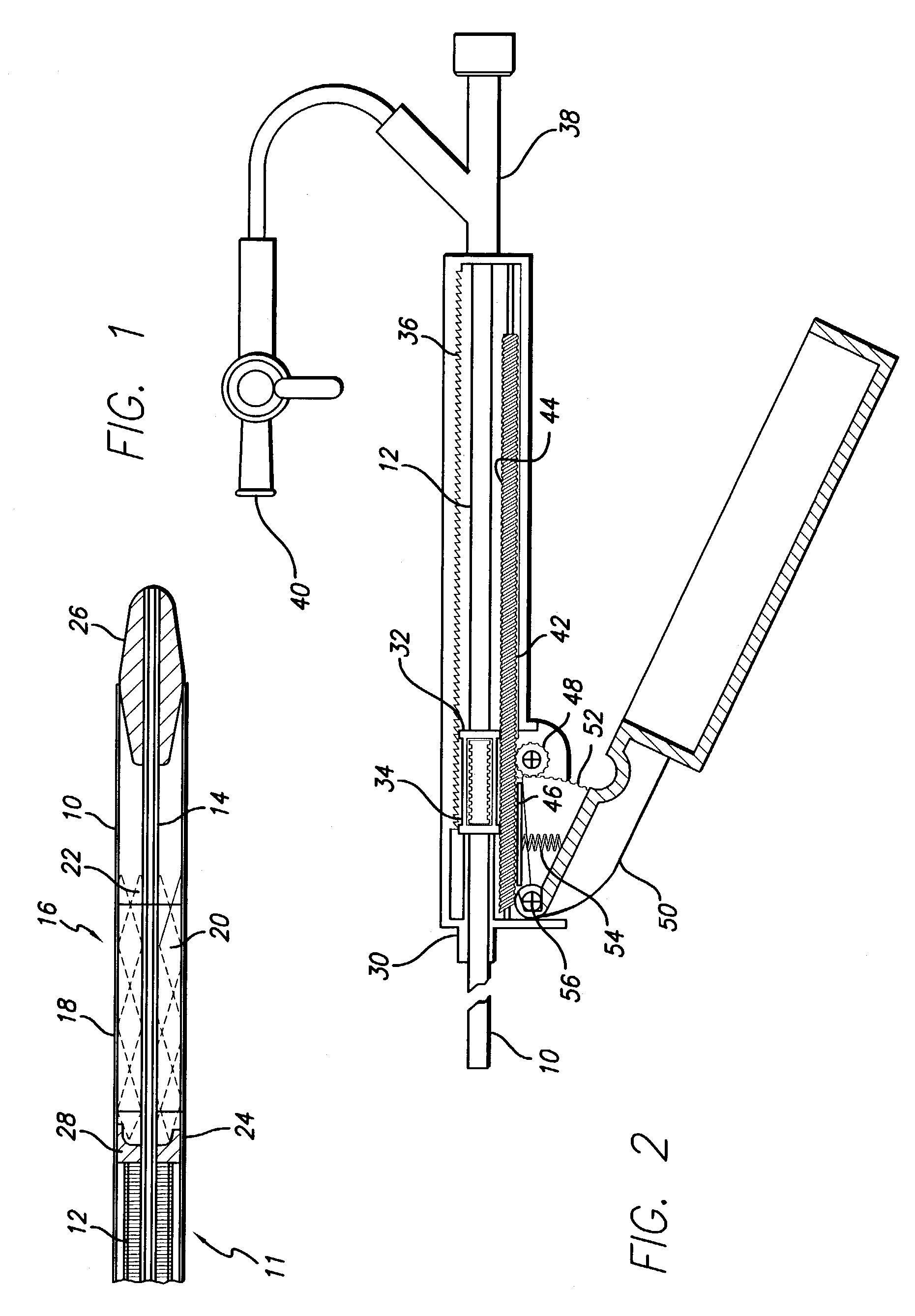
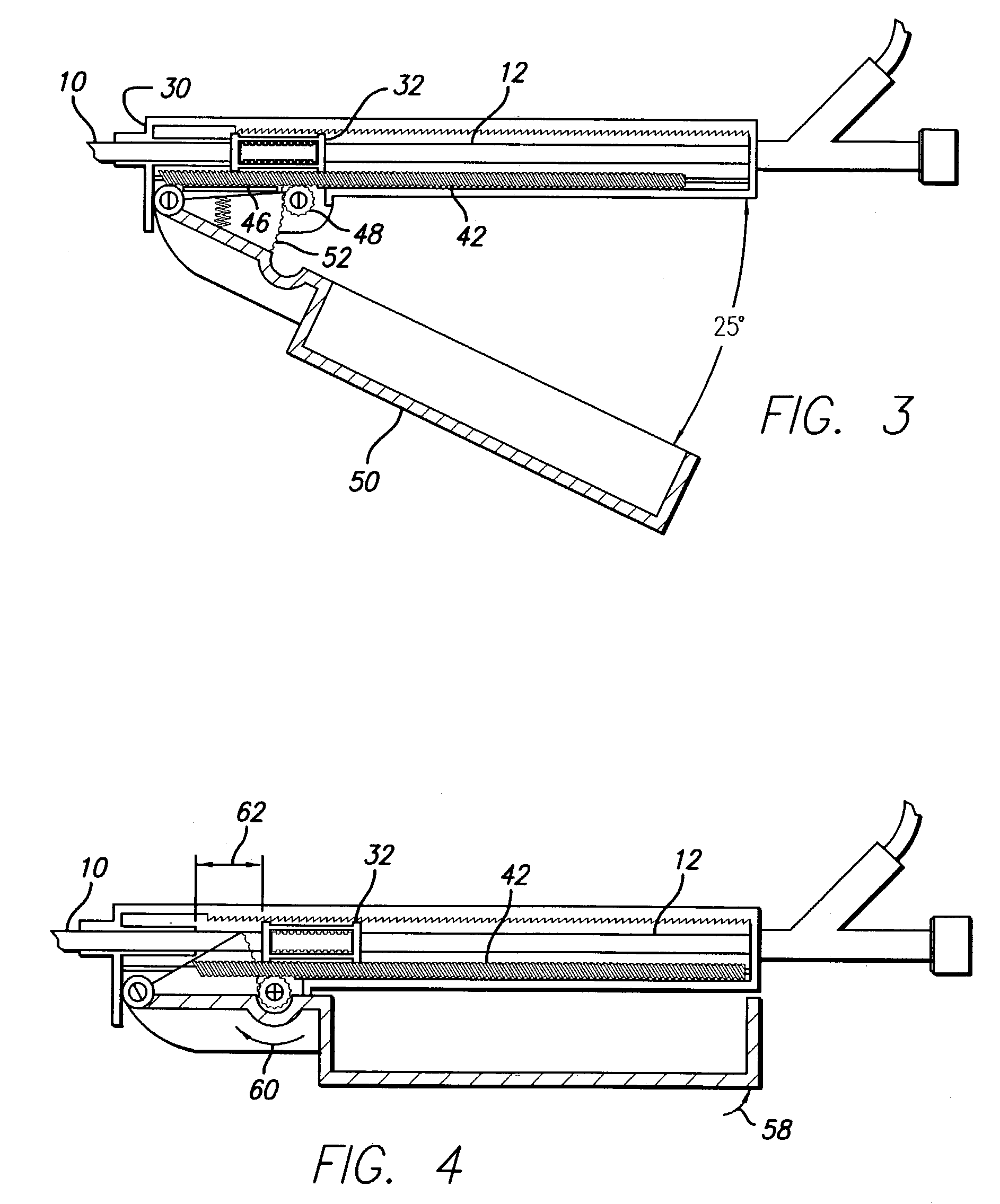
[0032]FIG. 2 illustrates a delivery mechanism for implanting the stent 16. This mechanism is generally in the form of a V-shaped lever device having a housing shell 30 from which the outer sheath 10 extends. The sheath 10 is secured to a pawl / sheath hub 32. A spring pawl 34 attached to the hub 32 engages a ratchet 36 which is integrated into the housing shell 30. Movement of the sheath hub 32 within the housing shell 30 is thus constrained to moving to the right as shown in FIG. 2. The tube spring 12 is secured in a fixed position to a guide wire port 38. The interior of the device may be. flushed by means of a flush stop cock 40. A ratchet rail 42 is provided at the bottom of the housing shell 30 and is reciprocal back and forth within the shell 30. The rail 42 includes ratchet teeth 44 on the upper side which engage with the spring pawl 34 and a rack gear 46 on the bottom surface thereof which engages a pinion 48. The pinion 48 is rotated by means of a lever handle 50 which includ...

second embodiment

[0037]the stent delivery mechanism is illustrated in FIG. 8. This delivery mechanism employs a hydraulic system to achieve extremely smooth operation. A housing 62 defines a reservoir chamber 64 within which is carried a piston 66. The outer sheath 10 is connected to the piston 66 to be moved therewith. A V-cup seal 68 prevents leakage of the hydraulic fluid carried within the housing. A piston displacement chamber 70 is defined between the piston 66 and the opening through which the sheath 10 exits.

[0038]Conduits 72 and 74 are coupled to opposite ends of the piston housing 62. Directional check valves 76 and 78 are contained within the conduits 72 and 74, respectively. A drive plunger 80 is contained within a plunger housing 82. Hydraulic fluid, such as saline solution, is provided through a port 84.

[0039]The operation of the hydraulic mechanism will be described with reference to FIGS. 9–12. In FIG. 9, the reservoir 64 is filled with fluid and the system is ready for operation. In...

third embodiment

[0042]Referring to FIGS. 13–16, the invention will be described. This embodiment employs a rack and pinion mechanism actuated by means of a thumb knob. In FIG. 13, the device includes a housing 82 within which is carried a rack 84, movable from left to right as illustrated in FIGS. 15 and 16. The rack 84 interacts with a rack drive gear 86 coupled to a reduction drive gear 88, which in turn is driven by a knob 90 having a gear 92. The outer sheath 10 is coupled to the rack 84 to be movable therewith. FIG. 14 is a cross-sectional view of FIG. 13 along line 14—14, showing a different perspective of knob 90 in relation to housing 82.

[0043]In operation, the knob 90 is rotated counterclockwise as illustrated in FIG. 15, causing the gear 92 to move in the same direction. This action causes the reduction drive gear 88 and the rack drive gear 86 to move in a clockwise position, which in turn causes the rack 84 to retract within the housing by a distance of approximately 1 cm per revolution ...


PUM


Abstract

A delivery mechanism for an implantable stent which provides a high mechanical advantage to the surgeon and convenient operation so as to facilitate smooth withdrawal of an outer catheter sheath following placement of the stent in the desired location within the patient's vessel. Preferred embodiments include a moving rail actuated by a V-shaped lever, a hydraulic actuator, a rack and pinion drive, and a power screw system. The delivery mechanism has a movable member that is attached to the outer catheter sheath so that actuating the mechanism results in an incremental movement of the moveable member, which in turn results in an incremental movement of the outer catheter sheath. Once the outer catheter sheath is retracted from the stent, the stent is deployed into the patient's vessel and the remaining parts of the mechanism, including an inner tube, an atraumatic tip, and a stabilizing element, are easily removed.

Description

CROSS-REFERENCE TO RELATED APPLICATIONS[0001]This application is a continuation of application Ser. No. 09 / 409,210, filed Sep. 30, 1999, now U.S. Pat. No. 6,514,261, which claims the benefit of provisional application Ser. No. 60 / 102,498, filed Sep. 30, 1998, each of which are expressly incorporated by reference herein.FIELD OF THE INVENTION[0002]The present invention relates to implantable medical devices. More particularly, the present invention relates to mechanisms for implanting a self-expanding stent graft which is used to sustain a weakened body vessel.BACKGROUND OF THE INVENTION[0003]Various diseases of blood vessels or hollow organs cause a stenosis or complete occlusion of their lumen, which results in a decrease or complete loss of their functional attributes. Various implantable prosthetic devices for sustaining a blood vessel or hollow organ lumen typically have a tubular-shaped frame body which is introduced into the vessel or hollow organ and fixed in the necessary lo...

Claims


Application Information

Patent Timeline
IPC IPC(8): A61F2/06A61F11/00A61F2/95
CPCA61F2/95A61F2/966A61F2002/9517A61F2/9517
Inventor RANDALL, SCOTT L.BROOKS, CHRISTOPHER J.MCCREA, BRENDAN J.VAN ROYEN, DONALD
Owner BARD PERIPHERAL VASCULAR
Why Eureka
Try Eureka