Method of and apparatus for electrostatic fluid acceleration control of a fluid flow

a technology of electrostatic fluid and acceleration control, which is applied in the direction of corona discharge, electric supply techniques, transportation and packaging, etc., can solve the problems of limiting ozone production, system and method of prior art being generally incapable of producing substantial airflow, and failing to recognize or appreciate the complexity of the ion generation process. , to achieve the effect of high frequency current flow, high voltage output, and high frequency rippl

Inactive Publication Date: 2006-10-17
KRONOS ADVANCED TECH
View PDF216 Cites 38 Cited by
  • Summary
  • Abstract
  • Description
  • Claims
  • Application Information

AI Technical Summary

Benefits of technology

[0020]To satisfy these requirements, the power supply and the corona generating device should be appropriately designed and configured. In particular, the power supply should generate a high voltage output with only minimal and, at the same time, relatively high frequency ripples. The corona generating device itself should have a predetermined value of designed, stray or parasitic capacitance that provides a substantial high frequency current flow through the electrodes, i.e., from one electrode to another. Should the power supply generate low frequency ripples, then Xc will be relatively large and the amplitude of the alternating component current will not be comparable to the amplitude of the direct current component of the current. Should the power supply generate very small or no ripple, then alternating current will not be comparable to the direct current. Should the corona generating device (i.e., the electrode array) have a low capacitance (including parasitic and / or stray capacitance between the electrodes), then the alternating current again will not be comparable in amplitude to the direct current. If a large resistance is installed between the power supply and the electrode array (see, for example, U.S. Pat. No. 4,789,801 of Lee, FIGS. 1 and 2), then the amplitude of the a.c. current ripples will be dampened (i.e., decreased) and will not be comparable in amplitude to that of the d.c. (i.e., constant) component of the current. Thus, only if certain conditions are satisfied, such that predetermined voltage and current relationships exist, will the corona generating device optimally function to provide sufficient air flow, enhanced operating efficiency, and desirable ozone levels. The resultant power supply is also less costly.
[0021]In particular, a power supply that generates ripples does not require substantial output filtering otherwise provided by a relatively expensive and physically large high voltage capacitor connected at the power supply output. This alone makes the power supply less expensive. In addition, such a power supply has less “inertia” i.e., less stored energy tending to dampen amplitude variations in the output and is therefore capable of rapidly changing output voltage than is a high inertia power supply with no or negligible ripples.

Problems solved by technology

The prior art fails to recognize or appreciate the fact that the ion generation process is more complicated than merely applying a voltage to two electrodes.
Instead, the systems and methods of the prior art are generally incapable of producing substantial airflow and, at the same time, limiting ozone production.

Method used


Image

  • Method of and apparatus for electrostatic fluid acceleration control of a fluid flow
  • Method of and apparatus for electrostatic fluid acceleration control of a fluid flow
  • Method of and apparatus for electrostatic fluid acceleration control of a fluid flow

Examples


Embodiment Construction

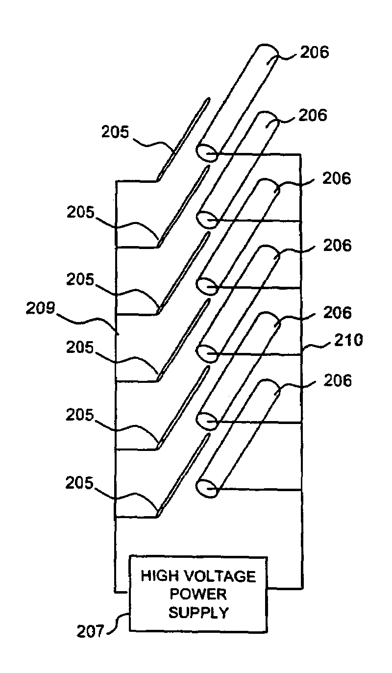
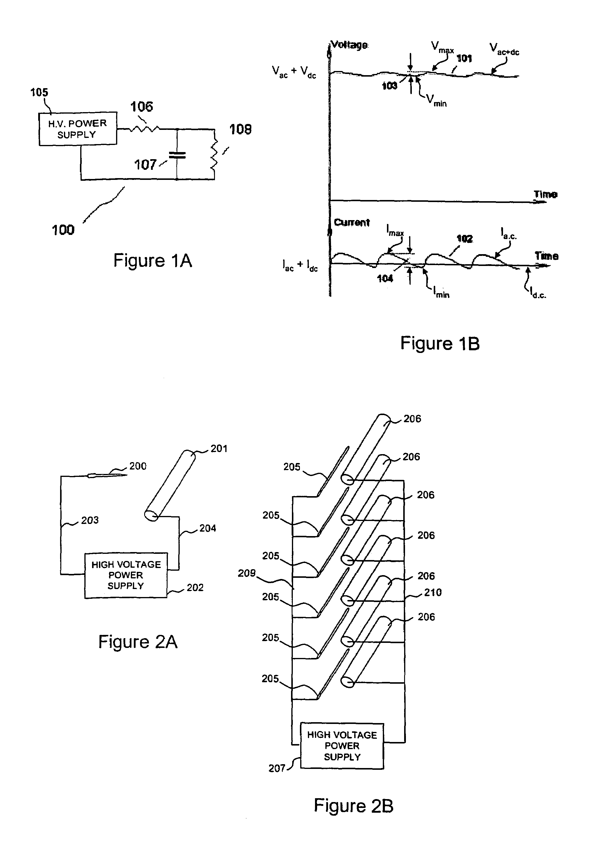
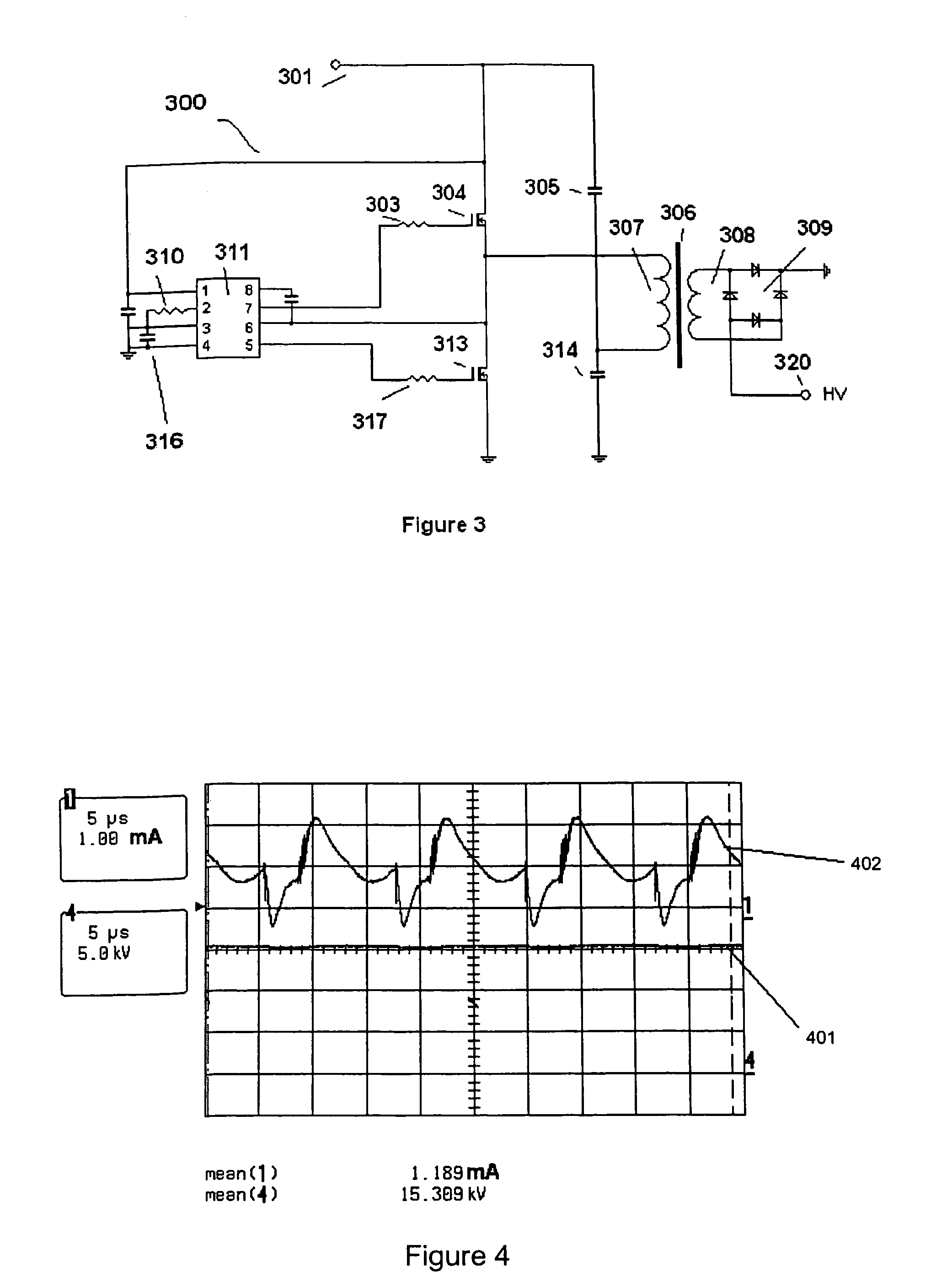
[0028]FIG. 1A is a block diagram of a power supply suitable to power a corona discharge device consistent with an embodiment of the invention. High voltage power supply (HVPS) 105 generates a power supply voltage 101 (FIG. 1B) of varying amplitude Vac+dc. Voltage 101 has superimposed on an average d.c. voltage of Vdc an a.c. or alternating component of amplitude Vac having an instantaneous value represented by the distance 103 (i.e., an alternating component of the voltage). A typical average d.c. component of the voltage 101 (Vdc) is in the range of 10 kV to 25 kV and more preferably equal to 18 kV. The ripple frequency “f” is typically around 100 kHz. It should be noted that low frequency harmonics, such as multiples of the 60 Hz commercial power line frequency including 120 Hz may be present in the voltage wave-form. The following calculation considers only the most significant harmonic, that is the highest harmonic, in this case 100 kHz. The ripples' peak-to-peak amplitude 103 (...


PUM


Abstract

A device for handling a fluid includes a corona discharge device and an electric power supply. The corona discharge device includes at least one corona discharge electrode and at least one collector electrode positioned proximate each other so as to provide a total inter-electrode capacitance within a predetermined range. The electric power supply is connected to supply an electric power signal to said corona discharge and collector electrodes so as to cause a corona current to flow between the corona discharge and collector electrodes. An amplitude of an alternating component of the voltage of the electric power signal generated is no greater than one-tenth that of an amplitude of a constant component of the voltage of the electric power signal. The alternating component of the voltage is of such amplitude and frequency that a ratio of an amplitude of the alternating component of the highest harmonic of the voltage divided by an amplitude of the constant component of said voltage being considerably less than that of a ratio of an amplitude of the highest harmonic of the alternating component of the corona current divided by an amplitude of the constant component of the corona current, i.e., (Vac/Vdc)≦(Iac/Idc).

Description

RELATED APPLICATIONS[0001]This application is a divisional of U.S. patent application Ser. No. 10 / 735,302 filed Dec. 15, 2003, and now U.S. Pat. No. 6,963,479 which is a continuation-in-part (CIP) of U.S. patent application Ser. No. 10 / 175,947 filed Jun. 21, 2002, now U.S. Pat. No. 6,664,741 issued Dec. 16, 2003 and is related to U.S. patent application Ser. No. 09 / 419,720 filed Oct. 14, 1999, now U.S. Pat. No. 6,504,308 issued Jan. 7, 2003 and incorporated herein in its entirety by reference.BACKGROUND OF THE INVENTION[0002]1. Field of the Invention[0003]The invention relates to electrical corona discharge devices and in particular to methods of and devices for fluid acceleration to provide velocity and momentum to a fluid, especially to air, through the use of ions and electrical fields.[0004]2. Description of the Related Art[0005]The prior art as described in a number of patents (see, e.g., U.S. Pat. No. 4,210,847 of Spurgin and U.S. Pat. No. 4,231,766 of Shannon, et al.) has rec...

Claims


Application Information

Patent Timeline
Patent Type & Authority Patents(United States)
IPC IPC(8): B03C3/68
CPCB03C3/49B03C3/68H01T19/00H05H1/24Y10S323/903H05H1/473
Inventor KRICHTAFOVITCH, IGOR A.
Owner KRONOS ADVANCED TECH
Why Eureka
Try Eureka