
Housing for electronic circuit

Inactive Publication Date: 2006-10-17
DENSO CORP
View PDF11 Cites 59 Cited by
  • Summary
  • Abstract
  • Description
  • Claims
  • Application Information

AI Technical Summary

Benefits of technology

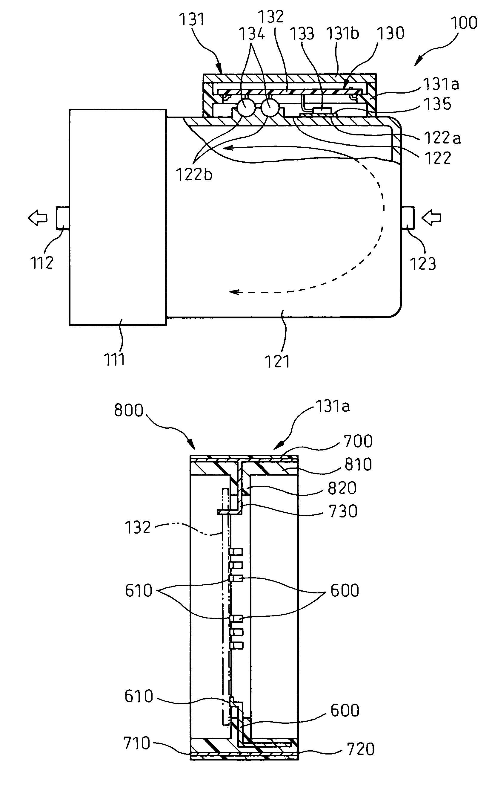
[0009]The bus bars (600) are integrated by insert-molding with the resin electronic circuit housing (131a), and therefore the electronic circuit housing (131a) is not bulky. Also, as the conductive plate (700) is insert-molded in the resin electronic circuit housing (131a) in such a position as to surround the space for containing the electronic circuit (130), electromagnetic waves can be shielded.
[0010]The electronic circuit housing (131a) having the bus bars (600) can shield the electronic magnetic waves and avoid the bulkiness.
[0012]The metal plate can positively shield electromagnetic waves, and also can improve the rigidity of the electronic circuit housing (131a). Further, as a metal generally has a higher heat conductivity than resin, the electronic circuit (130) can be more easily cooled.
[0017]That part of the electric compressor (100) in which the refrigerant sucked by the compression mechanism (110) flows is comparatively low in temperature. Therefore, the conductive plate (700) in contact with this part is easily cooled so that the electronic circuit (130) contained in the electronic circuit housing (131a) is cooled more easily.

Problems solved by technology

The conventional electronic circuit housing, however, being a resin housing, poses the problem that electromagnetic waves generated by the electronic circuit are radiated outside of the housing or an external electromagnetic noise is received by the electronic circuit in the housing.
As bus bars cannot be formed integrally with a conductive housing, however, the electronic circuit housing becomes undesirably bulky.

Method used


Image

  • Housing for electronic circuit
  • Housing for electronic circuit
  • Housing for electronic circuit

Examples


Embodiment Construction

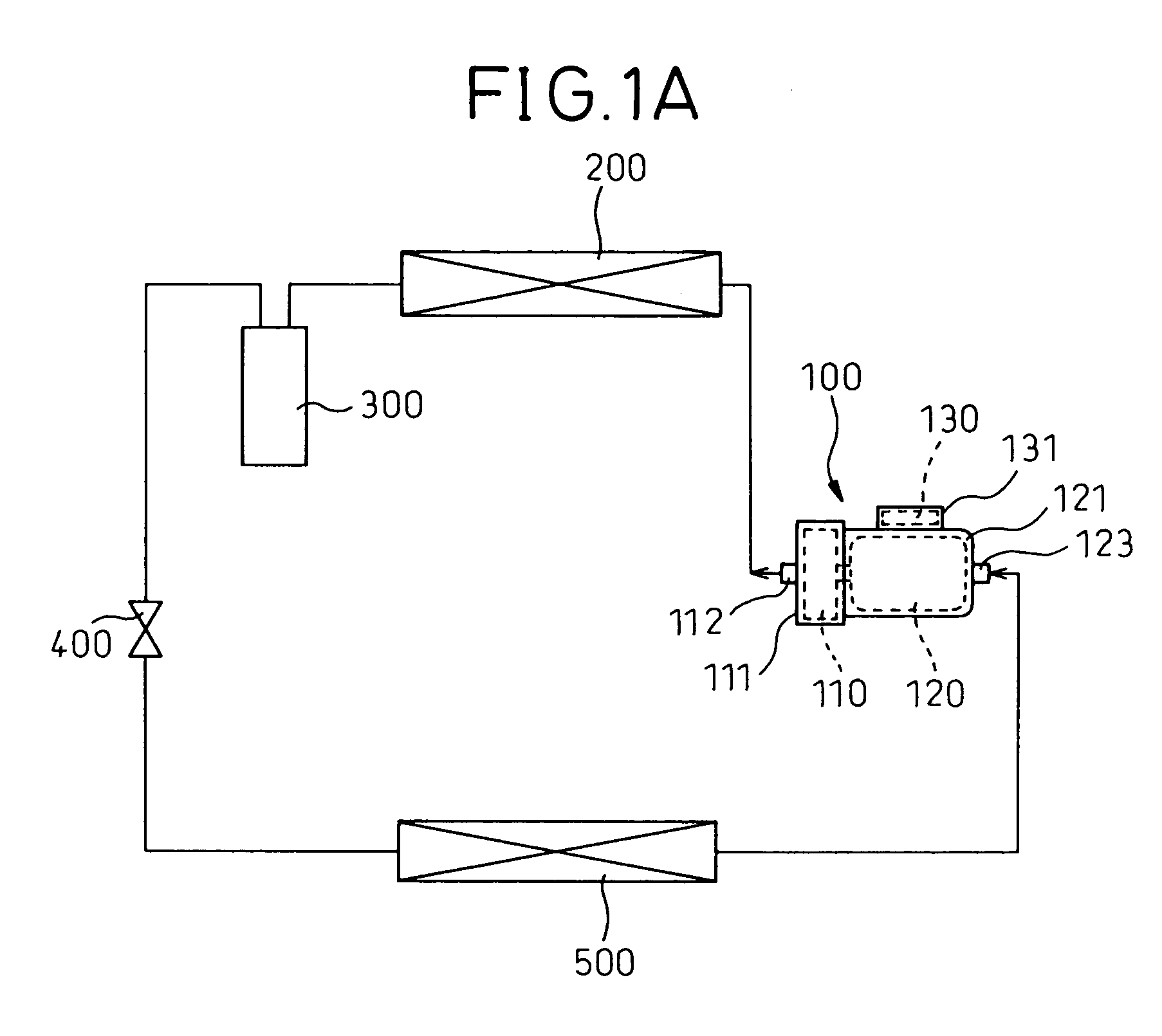
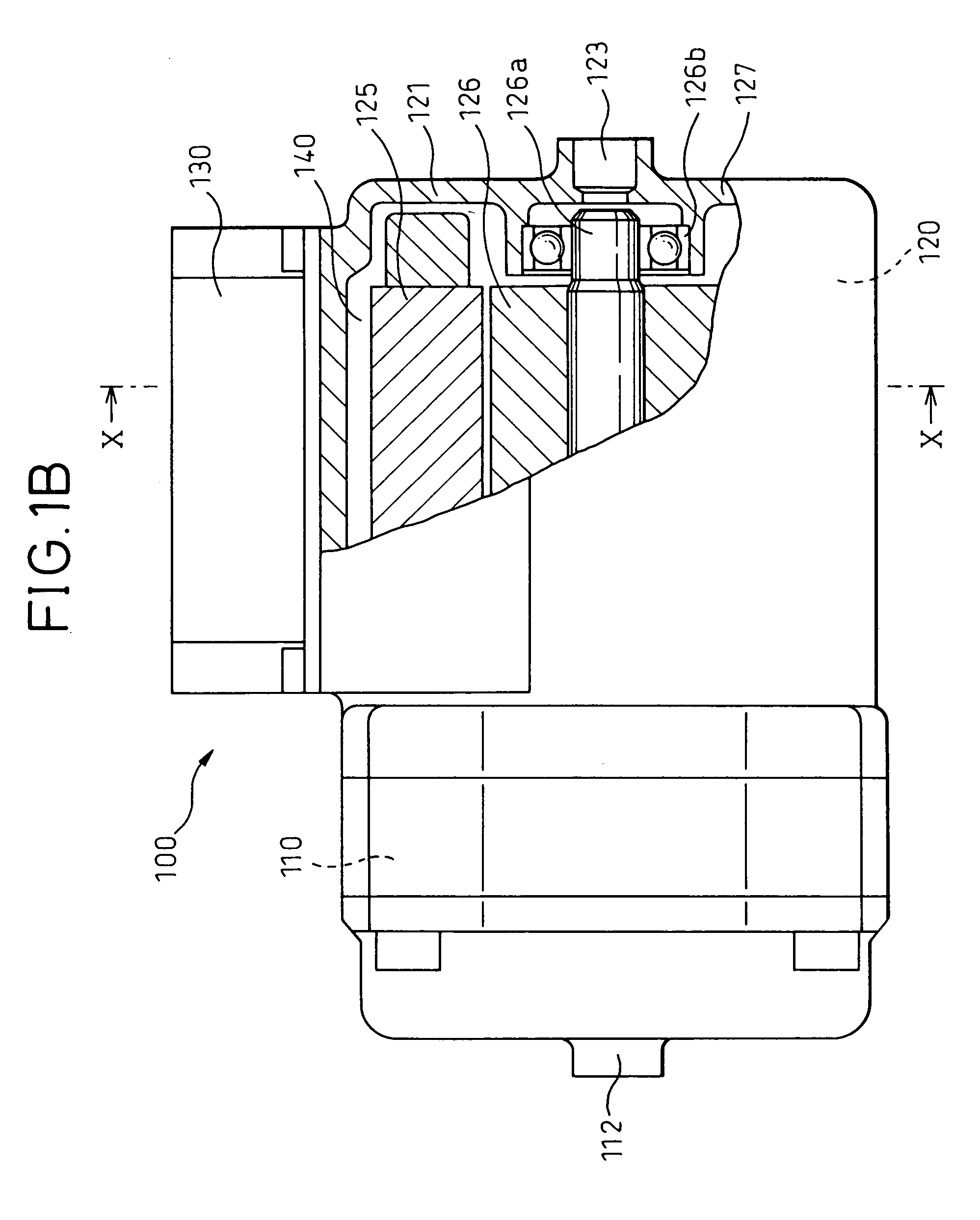
[0025]FIG. 1A is a schematic diagram showing a vapor pressure compression refrigeration cycle for vehicles using a electric compressor 100 with a motor driving circuit having an electronic circuit housing according to this invention.

[0026]Reference numeral 200 designates a heat radiator (condenser) for cooling the refrigerant discharged from the compressor 100. Numeral 300 designates a receiver (gas-liquid separator) for separating the refrigerant flowing out of the heat radiator 200 into a gas-phase refrigerant and a liquid-phase refrigerant and supplying the liquid-phase refrigerant while at the same time storing extraneous refrigerant generated during the refrigeration cycle.

[0027]Numeral 400 designates an expansion valve constituting a pressure reducing means for reducing the pressure of the liquid-phase refrigerant that has flowed out of the receiver 300. Numeral 500 designates an evaporator for evaporating the refrigerant reduced in pressure by the expansion valve 400. Althoug...


PUM


Abstract

A box unit is a housing having a space for containing a circuit board therein. Bus bars are insert-molded in a resin body of the box. A metal shield plate is insert-molded around the entire periphery of the box and outside the bus bars. As a result, the box has a shield and is reduced in size compared with a metal box.

Description

BACKGROUND OF THE INVENTION[0001]1. Field of the Invention[0002]The present invention relates to a resin housing for containing an electronic circuit and, more particularly, to a resin housing for containing a motor driving circuit for an electric compressor.[0003]2. Description of the Related Art[0004]A conventional electronic circuit housing is disclosed in Japanese Unexamined Patent Publication No. 2000-159083. This housing is illustrated as a resin housing having bus bars insert-molded therein for connecting the electronic circuit in it.[0005]The conventional electronic circuit housing, however, being a resin housing, poses the problem that electromagnetic waves generated by the electronic circuit are radiated outside of the housing or an external electromagnetic noise is received by the electronic circuit in the housing.[0006]An electronic circuit housing which is formed of a metal to cope with this problem can produce the effect of shielding an electromagnetic wave. As bus bar...

Claims


Application Information

Patent Timeline
IPC IPC(8): H02K5/00H02B1/26H02B1/56H02K11/00H02K5/24H02K9/00H05K7/20H05K9/00F04B39/00B60R16/02B60R16/023F04C29/00H02K11/04H05K1/02
CPCB60R16/0239H02K11/0005H02K11/0073H05K1/0263H05K1/0218H05K2201/09118H05K2201/09754H05K2201/0999H05K2201/10272H05K2201/2018H02K11/0141H02K11/33
Inventor SHINDO, YUSUKE
Owner DENSO CORP
Learn More