Ceramic heaters, a method for producing the same and articles having metal members

a ceramic heater and metal member technology, applied in the direction of ohmic-resistance heating, hot plate heating arrangement, coating, etc., can solve the problem of off-specification product generation in an actual mass production process, and achieve the effect of reducing the generation of irregular carbide, reducing the production of irregular carbide, and reducing the yield of off-specification products

Inactive Publication Date: 2006-10-24
NGK INSULATORS LTD
View PDF7 Cites 21 Cited by
  • Summary
  • Abstract
  • Description
  • Claims
  • Application Information

AI Technical Summary

Benefits of technology

[0032]It was further found that the carbide generation may be reduced by applying a lower pressure at a temperature at which AlN does not decompose in the sintering process. It was further found that such low temperature sintering condition may be effectively combined with the dummy member.
[0033]Further, such idea of reducing the irregular carbide generation in the heat generator due to the absorption of excessive carbon atoms into the dummy member is applicable to the heat generator and ceramic heater, as well as the other ceramic articles having metal members. That is, when the metal member contains one or more metal element(s) selected from the group consisting of elements belonging to IVa, Va and Via groups of the Periodic Table, the dummy member may be contacted with the shaped body of ceramic powder. The dummy member is composed of a metal containing one or more metal element(s) selected from the group consisting of elements belonging to IVa, Va and Via groups of the Periodic Table. The shaped body is then sintered to prevent irregular carbide generation in the metal member so that the yield of off-specification products may be reduced.

Problems solved by technology

Even in this case, however, it is proved that the uniformity of temperature on the heating face may be deteriorated to result in the generation of off-specification products in an actual mass production process.

Method used


Image

  • Ceramic heaters, a method for producing the same and articles having metal members
  • Ceramic heaters, a method for producing the same and articles having metal members
  • Ceramic heaters, a method for producing the same and articles having metal members

Examples


examples

(Experiment A)

[0068]The ceramic heater 15 shown in FIG. 5 was produced. The substrate was made of an aluminum nitride sintered body 4A having a diameter φ of 350 mm and a thickness of 25 mm. The heat resistors 5A and 5B each having a shape of a coil spring was embedded in the substrate 4A. The terminals 6A to 6D were composed of cylindrical terminals made of molybdenum, respectively. 5 weight percent of yttria powder having a mean particle diameter of 1.5 μm and a purity of 99.9 percent was added to aluminum nitride powder having a mean particle diameter of 1 μm and a purity of 99.9 percent to obtain mixed powder. The mixed powder was press molded to produce a shaped body having the heat resistor embedded therein. The shaped body was sintered by means of hot pressing at a pressure of 200 kgf / cm2 and a temperature of 1800° C.

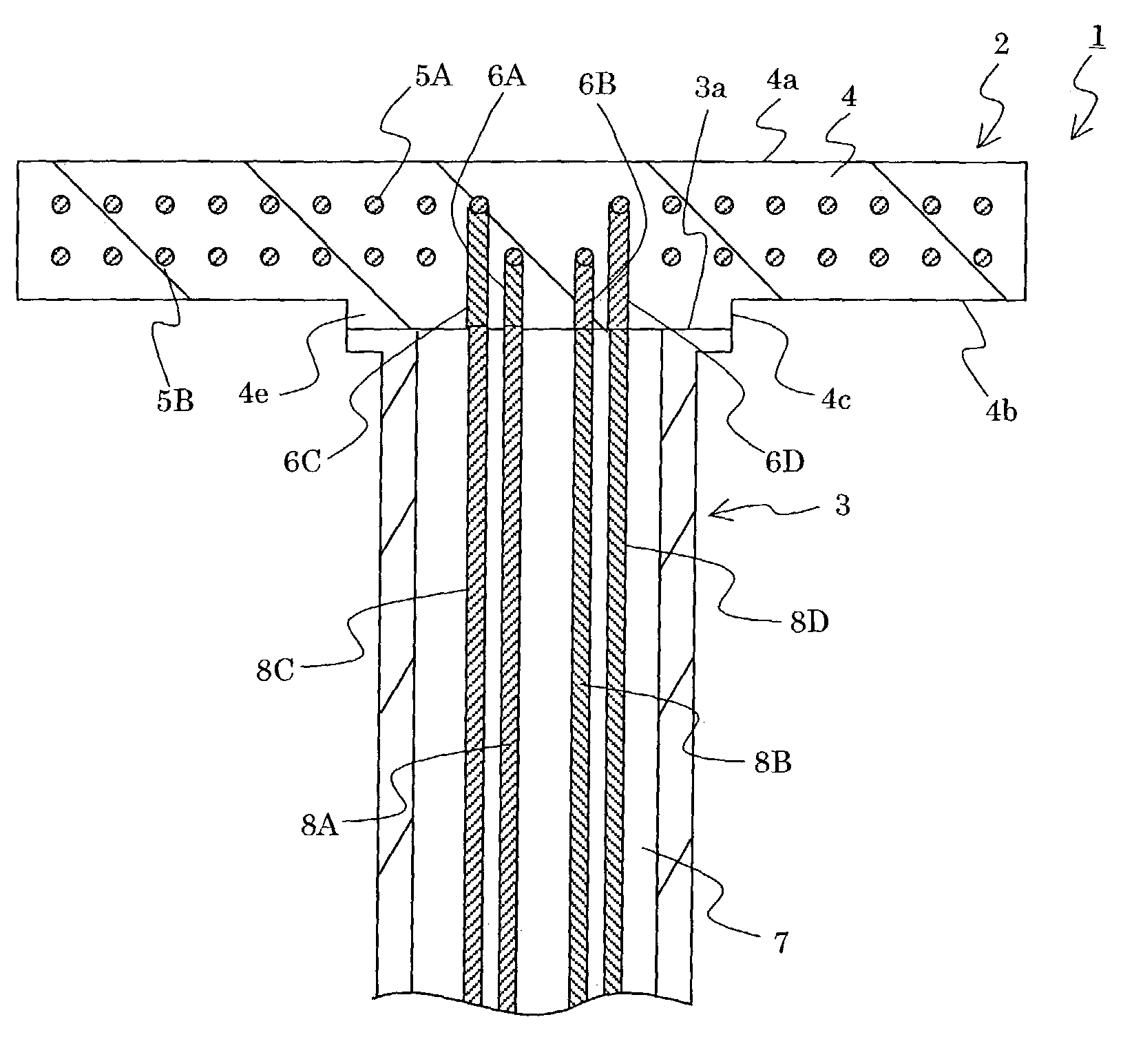
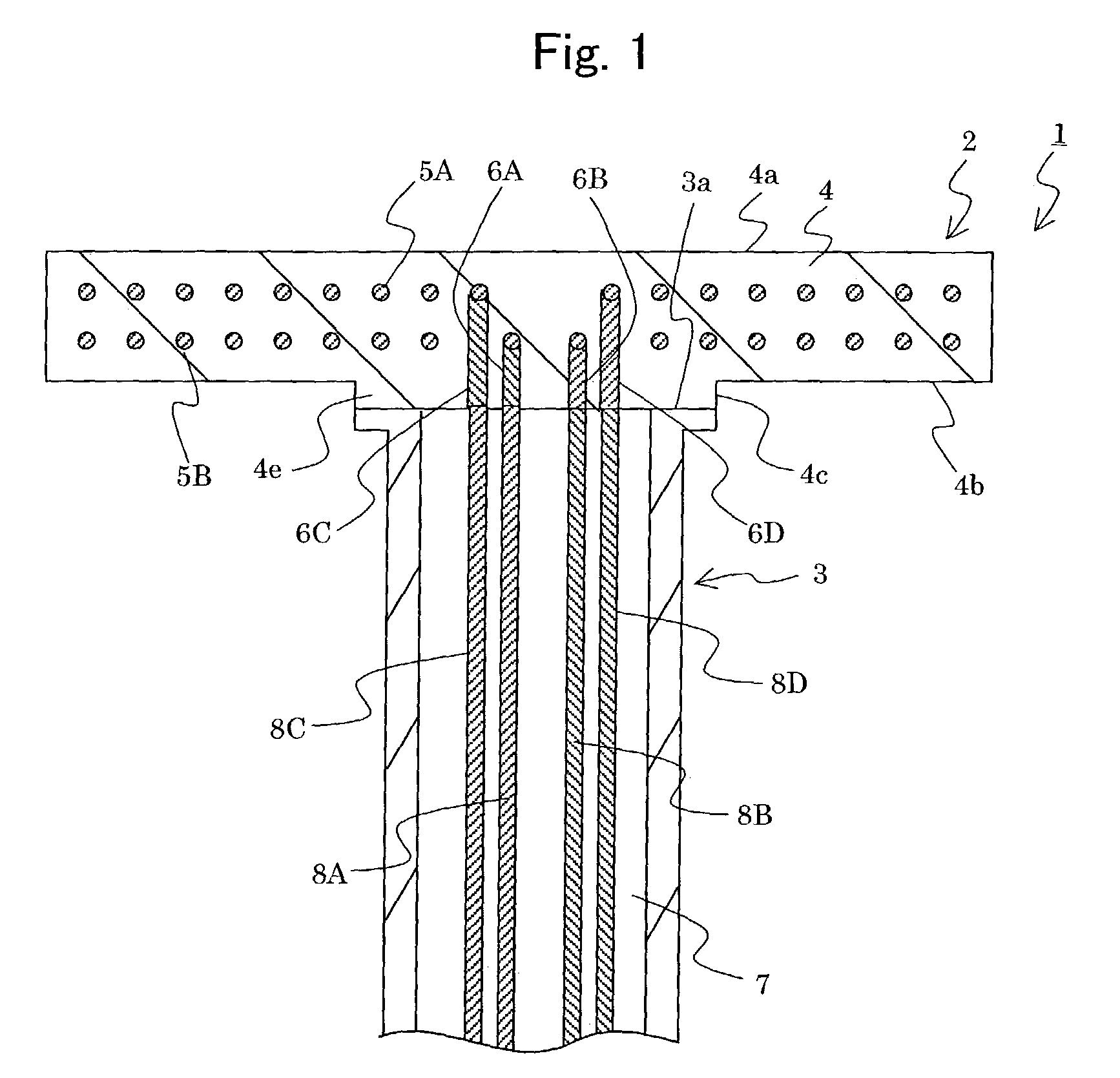
[0069]The ceramic heater 15 was joined with the supporting member 3 shown in FIG. 1. The supporting member 3 is composed of an aluminum nitride sintered body hav...

experiment b

(Experiment B)

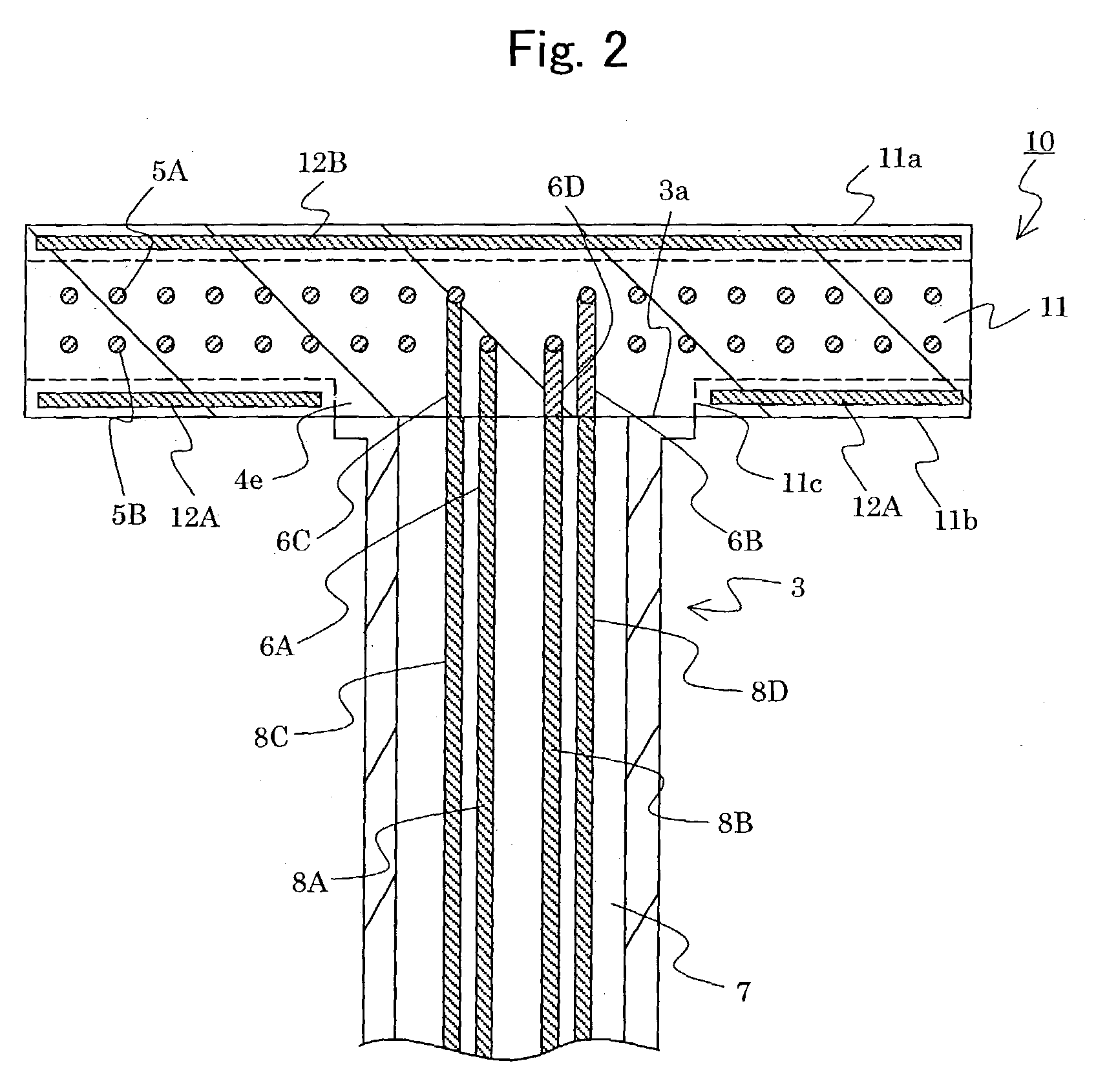
[0074]The heating system 1 shown in FIG. 1 was fabricated according to the method described referring to FIGS. 1 and 2. Specifically, 5 weight percent of yttria powder having a mean particle diameter of 1.5 μm and purity of 99.9 percent was added to and mixed with aluminum nitride powder having a mean particle diameter of 1 μm and purity of 99.9 percent. The thus obtained mixed powder was pressed to obtain a shaped body. The heat resistors 5A, 5B, terminals 6A to 6D and dummy members 12A and 12B were embedded in the shaped body in this step. The heat resistor had a shape of a coil spring and made of molybdenum. Each of the terminals 6A to 6D was a cylindrical terminal made of molybdenum. The dummy member 12A was composed of a ring-shaped plate made of molybdenum having an outer diameter of 348 mm and an inner diameter of 100 mm. The dummy member 12B was composed of a circular plate having an outer diameter of 348 mm. The shaped body was sintered by hot pressing at a pr...

experiment c)

(Experiment C)

[0080]Two samples of the heating systems were fabricated according to the same procedure as the experiment B. The dummy members 12A and 12B were not embedded in the substrate. The resistances of the heat resistor before and after the sintering process, the ratio (Ic / Im) of the strengths of main strength peaks of molybdenum and the carbide, and the difference of maximum and minimum temperatures on the heating face were measured for each system. The results were shown in table 3.

[0081]

TABLE 3ComparativeComparativeExample 1Example 2Presence of dummy Member NoneNoneHeatResistance Before2.81.7Resistor 5 ASintering (Ω)Resistance After3.92.5Sintering (Ω)Ratio of change of3947Resistance (%)HeatResistance Before2.81.6Resistor 5 BSintering (Ω)Resistance After3.92.5Sintering (Ω)Ratio of change of3956Resistance (%)Ratio of peak Intensities Ic / Im 0.310.37Difference of Temperature on Heating 2733face (° C.) 

[0082]As can be seen from table 3, when the dummy member is not embedded in ...


PUM

PropertyMeasurementUnit
weight percentaaaaaaaaaa
temperatureaaaaaaaaaa
pressureaaaaaaaaaa

Abstract

A ceramic heater is provided including a ceramic sintered body and a heat resistor embedded in the substrate, wherein a change in the temperature uniformity on the heating face is reduced. The heat resistor contains a metal comprising one or more metal elements selected from the group consisting of Group IVa, Group Va and Group VIa elements of the Periodic Table and a carbide of the metal. A ratio (Ic/Im) of a total strength (Ic) of main peak of the metal carbide to a total strength (Im) of main peak strength of the metal is not larger than 0.2. Alternatively, the ratio (Rb−Ra)/Ra is not larger than 30 percent, where “Ra” is the resistance of the heat resistor before sintering and “Rb” is the resistance of the heat resistor after sintering.

Description

[0001]This application claims the benefits of Japanese Patent Application P2002-88585 filed on Mar. 27, 2002, the entirety of which is incorporated by reference.BACKGROUND OF THE INVENTION[0002]1. Field of the Invention[0003]The invention relates to a ceramic heater, a method of producing the same and an article having a metal member.[0004]2. Related Art Statement[0005]In a semiconductor producing system, ceramic heaters have been applied to heat a wafer so as to deposit a semiconductor thin film on the wafer from gaseous raw materials such as silane gas by means of thermal CVD or the like. For example, Japanese Patent publication P2000-68, 038A disclosed this kind of ceramic heater. The heater has a substrate made of a nitride ceramics and a heat resistor made of, for example, tungsten. A tungsten silicide and tungsten carbide layers are formed in the heat resistor during the sintering process of the ceramic substrate.[0006]Japanese Patent publication 11-251, 039A discloses a heate...

Claims


Application Information

Patent Timeline
Patent Type & Authority Patents(United States)
IPC IPC(8): H05B3/68H05B3/00H01L21/00H05B3/12H05B3/14H05B3/18H05B3/74
CPCH01L21/67103H05B3/143H05B3/12Y10T29/49083H01L21/205
Inventor YAMAGUCHI, SHINJINOBORI, KAZUHIRO
Owner NGK INSULATORS LTD
Why Eureka
Try Eureka