Distributed gain network

a gain network and distribution network technology, applied in the direction of gated amplifiers, amplifiers with coupling networks, two-way working systems, etc., can solve the problems of large power consumption, complex devices for amplification of each stage, and increase the demand for amplifiers, so as to achieve low noise, simple amplifier devices, and low power amplification

Inactive Publication Date: 2006-10-24
WAVESTAR COMM SYST LLC
View PDF2 Cites 11 Cited by
  • Summary
  • Abstract
  • Description
  • Claims
  • Application Information

AI Technical Summary

Benefits of technology

[0016]One of the advantages of the present invention is that lower power amplification is required than previous networks due to the spacing and low introduction of noise to the system. The lower power enables simpler amplifier devices that consume much less power and therefore affordable battery backup may enable the device to operate when power is lost. Further, a wireless communication capability may allow neighboring devices to transmit all or a portion of the communication traffic from one device to another (heal) in the event of a cable cut or failure. The amplifiers may be connected and installed without performing complex analysis of each amplifier installation, significantly reducing the training and educational requirements of installation technicians.

Problems solved by technology

As the bandwidth needs of the network increase, the demands on the amplifiers also increase.
However, the amplification of each stage requires complex devices that commonly consume a large amount of power.
These amplifiers require large amounts of power because the signal must be amplified sufficiently to traverse the larger distances.
Layout and installation of conventional networks is complex and cumbersome.
This may require expensive analytical equipment to be brought into the field to determine appropriate equalizer or attenuator settings for each amplifier.
One of the weaknesses of the typical cable telecommunications network is the vulnerability to failure.
If a failure were to occur in the network, either by having a cable cut or by failure of one of the amplifiers, significant outages may occur.
If a cable is damaged in a conventional network, there are no alternate routes by which signals may bypass the damage, leaving all of the downstream subscribers without service until a repair may be instituted.
Similarly, if a single amplifier should fail, the large spacing between the amplifiers may prohibit a signal from reaching the next cascaded amplifier with sufficient signal, thereby resulting in similar downstream signal loss.

Method used


Image

  • Distributed gain network
  • Distributed gain network
  • Distributed gain network

Examples


embodiment 100

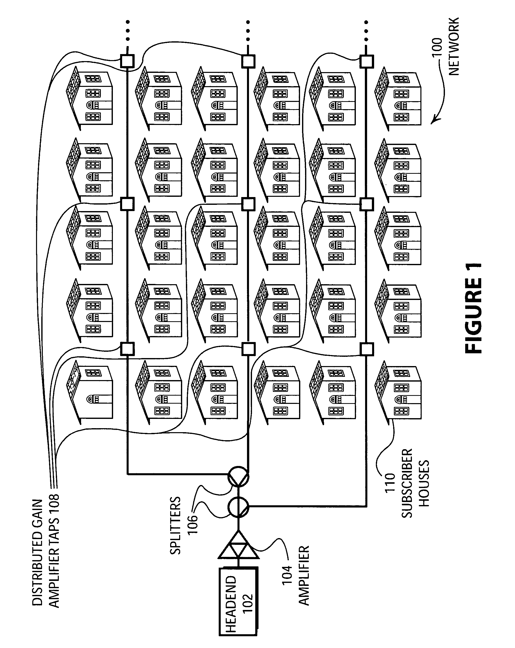
[0026]FIG. 1 illustrates an embodiment 100 of the present invention of a distribution network 100. Cable and Digital Subscriber Lines (DSL) require “substantially linear” networks to carry highly complex modulation formats that mix amplitude, phase and frequency modulation (AM, PM and FM), which are also multi-carrier with high signal spectral densities. Systems for communicating information from a client device to a substantially linear broadband network have been contemplated in U.S. Pat. No. 6,377,782 issued to Bishop et al., which is hereby incorporated by reference for all it teaches and discloses. Cable telecommunication networks are made of long spans of coaxial and fiber cables, which are inherently subject to high signal loss. To replace lost signal amplitude (and maintain minimum signal-to-noise ratios) amplifiers are necessary. A purely linear amplifier, that is an amplifier with no non-linear terms in its gain equation, will simply increase the amplitude of all signals e...

embodiment 200

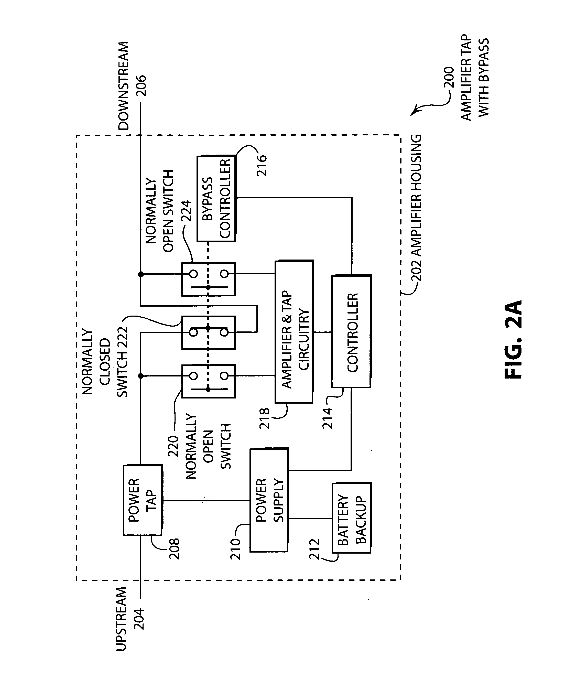
[0030]FIG. 2A illustrates an embodiment 200 of the present invention of an amplifier with a bypass mode. The amplifier housing 202 has an upstream input 204 and a downstream output 206. In many cases, bidirectional signals may be carried on both the upstream connection 204 and the downstream connection 206. A power tap 208 normally takes low frequency AC power off of the cable and transfers the power to a power supply 210 connected to a battery backup 212. A controller 214 connects to a bypass controller 216 to the amplifier tap and circuitry 218. The upstream signal is connected to a normally open switch 220, a normally closed switch 222, and a second normally open switch 224. The bypass controller 216 is operable to actuate the three switches 220, 222, and 224 in unison.

embodiment 201

[0031]FIG. 2B illustrates an embodiment 201 of the present invention of an amplifier with a bypass mode. The amplifier housing 202 has an upstream input 204 and a downstream output 206. In many cases, bidirectional signals may be carried on both the upstream connection 204 and the downstream connection 206. A power tap 208 normally takes low frequency AC power off of the cable and transfers the power to a power supply 210 connected to a battery backup 212. A controller 214 connects to a bypass controller 216 to the amplifier tap and circuitry 218. The upstream signal is connected to the switch 226, and a second switch 228. The switches 226 and 228 are capable of switching between the amplifier and tap circuitry 218 and the bypass circuit 230.

[0032]The embodiment 200 is an amplifier that is adapted to allow signals to bypass the amplifier and tap circuitry 218 when no power is applied to the amplifier, i.e., when the switches 220, 222 and 224 revert to their respective normal states ...


PUM


Abstract

A system and method for a distribution network is provided wherein cascaded power amplifiers with bypass switching are disposed along the branches of the network. The amplifiers may have an RF modem and a programmable digital computer that enables communication with a headend or a controlling computer as well as a bypass switch control for disabling the amplification function of the amplifiers. The amplifier may have a wireless communication system for communicating with individual subscriber's homes and communicating with a neighboring amplifier system for use in emergency situations or during installation and configuration of the network. The network comprised of the amplifiers may have redundant signal paths, using the wireless communication devices of the amplifiers, which may be used as backup signal paths for certain communications requiring high uptime such as telephony.

Description

CROSS REFERENCE TO RELATED CASES[0001]The present patent application is based upon and claims the benefit of U.S. Provisional Patent Application Ser. No. 60 / 466,810, filed on Apr. 29, 2003, entitled “Distributed Gain Network” by Donald M. Bishop, which is hereby specifically incorporated herein by reference for all that it discloses and teaches.BACKGROUND OF THE INVENTION[0002]1. Field of the Invention[0003]The present invention pertains to distribution networks and specifically to substantially linear broadband networks such as cable telecommunications networks.[0004]2. Description of the Background[0005]Amplifiers are typically cascaded along the coaxial portion of a hybrid fiber coaxial (HFC) cable telecommunications distribution networks. The amplifiers are typically spaced as far apart as possible. As the bandwidth needs of the network increase, the demands on the amplifiers also increase. The trend to place amplifiers as far apart as possible has the advantage that fewer devic...

Claims


Application Information

Patent Timeline
Patent Type & Authority Patents(United States)
IPC IPC(8): H03F3/68G01S1/00H03F1/00H03F3/72H04B1/74H04B3/54H04H1/00H04H20/78H04N7/173
CPCG01S1/00H03F3/72H04B1/74H04B1/745H04B3/36H04B3/542H04H20/78H04N7/17309H03F2203/7231H03F2203/7239H04B2203/5445H04B2203/5483H04N7/104H04N21/6118H04N21/6168
Inventor BISHOP, DONALD M.
Owner WAVESTAR COMM SYST LLC
Why Eureka
Try Eureka