Slot coupling patch antenna

a patch antenna and slot technology, applied in the field of antennas, can solve the problems of obstructing the view of the driver of the vehicle, disappointing performance of the antenna integrated with the automotive glass in receiving sdars signals, etc., and achieves the effects of low axial ratio, high radiation gain, and excellent performance characteristics

Inactive Publication Date: 2006-10-24
AGC AUTOMOTIVE AMERICAS
View PDF32 Cites 13 Cited by
  • Summary
  • Abstract
  • Description
  • Claims
  • Application Information

AI Technical Summary

Benefits of technology

[0011]The structure of the antenna of the subject invention provides excellent performance characteristics when receiving a circularly polarized RF signal. These characteristics include high radiation gain, a low axial ratio, and high radiation efficiency. The antenna of the subject invention may be integrated with a window of a vehicle. As a result, the antenna is generally conformal with the window and is relatively compact, occupying a relatively small area of the window, yet still providing a high performance when receiving the circularly polarized RF signal. Therefore, the antenna is desirable for automotive manufacturers and a driver of the vehicle.

Problems solved by technology

The antenna of the '645 patent occupies a relatively large area on the pane of glass, which obstructs the view of a driver of the vehicle.
The characteristics of glass, particularly soda-lime-silica automotive glass, and the angled disposition of this glass when applied as a window of a vehicle, provide challenges to the effective integration of an antenna with a window of the vehicle.
To date, the performance of antennas integrated with automotive glass in receiving SDARS signals has been disappointing.

Method used


Image

  • Slot coupling patch antenna
  • Slot coupling patch antenna
  • Slot coupling patch antenna

Examples


Embodiment Construction

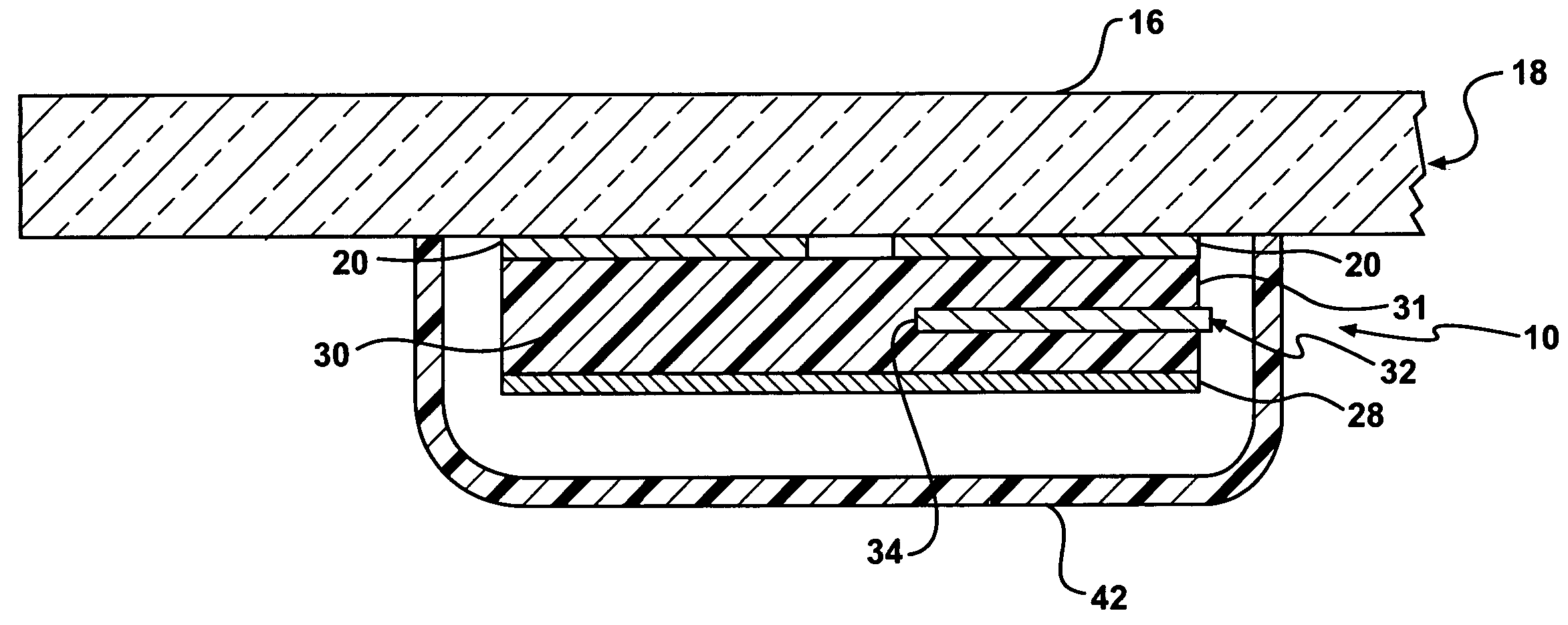
[0022]Referring to the Figures, wherein like numerals indicate like parts throughout the several views, an antenna is shown generally at 10. In the preferred embodiment, the antenna 10 is utilized to receive a circularly polarized radio frequency (RF) signal from a satellite. Those skilled in the art realize that the antenna 10 may also be used to transmit the circularly polarized RF signal. Specifically, the preferred embodiment of the antenna 10 receives a left-hand circularly polarized (LHCP) RF signal like those produced by a Satellite Digital Audio Radio Service (SDARS) provider, such as XM® Satellite Radio or SIRIUS® Satellite Radio. However, it is to be understood that the antenna 10 may also receive a right-hand circularly polarized (RHCP) RF signal. Furthermore, the antenna 10 may also be utilized to transmit or receive a linear polarized RF signal.

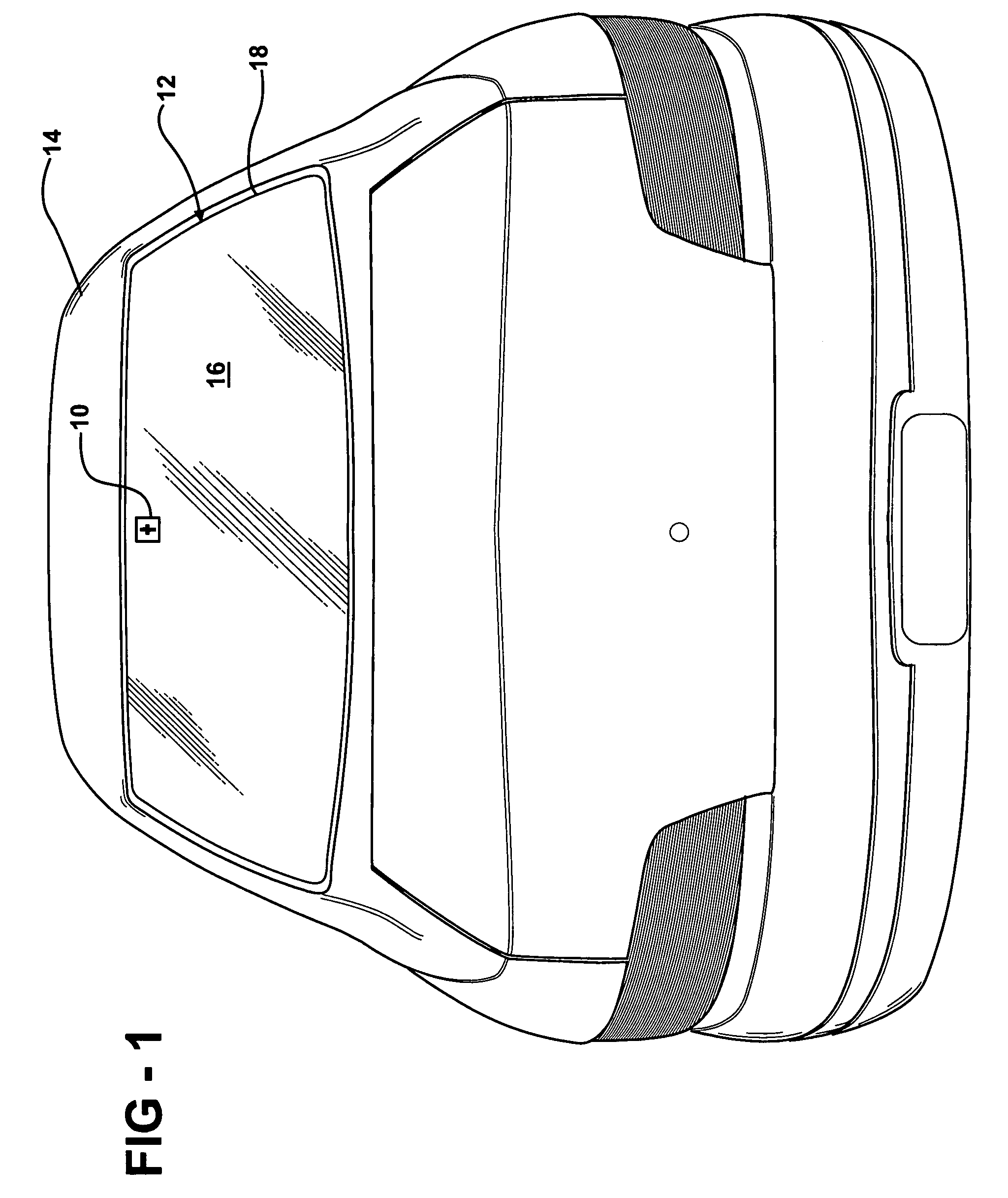
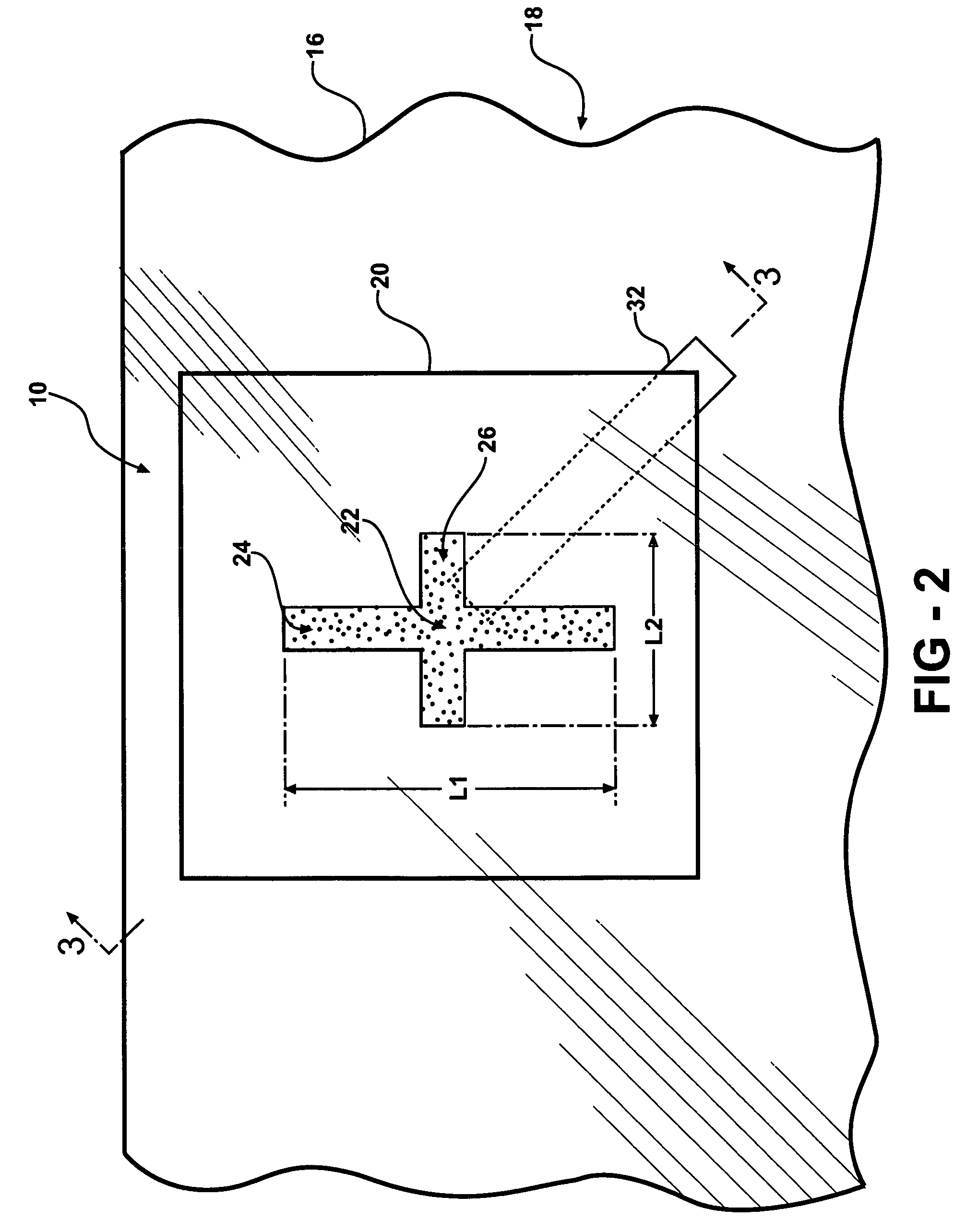
[0023]Referring to FIG. 1, the antenna 10 is preferably integrated with a window 12 of a vehicle 14. This window 12 may be a re...


PUM


Abstract

An antenna for receiving and / or transmitting circularly and / or linearly polarized RF signals includes a radiation element, a ground plane, a dielectric substrate, and a feed line. The radiation element is disposed on a pane of glass. The radiation element defines a slot having a first leg and a second leg forming the shape of a cross for generating the circular and / or linear polarization. The cross-shaped slot includes a center point. The ground plane is disposed substantially parallel to and spaced from the radiation element. The dielectric substrate is sandwiched between the radiation element and the ground plane. The feed line extends within the dielectric substrate and is electromagnetically coupled with the radiation element and the ground plane. The feed line terminates at a distal end short of the center point of the slot. That is, the feed line does not cross the center point. The antenna is compact in size and generally conformal to the pane of glass.

Description

BACKGROUND OF THE INVENTION[0001]1. Field of the Invention[0002]The subject invention relates to an antenna, specifically a planar slot coupling patch antenna, for receiving a circularly polarized radio frequency (RF) signal from a satellite.[0003]2. Description of the Prior Art[0004]Vehicles have long implemented glass to enclose a cabin of the vehicle while still allowing visibility for the driver of the vehicle. Automotive glass is typically either a tempered (or toughened) glass or a laminated glass which is produced by bonding two or more panes of glass together with a plastic interlayer. The interlayer keeps the panes of glass together even when the glass is broken.[0005]Recently, antennas have been integrated with the glass of the vehicle. This integration helps improve the aerodynamic performance of the vehicle as well to help present the vehicle with an aesthetically-pleasing, streamlined appearance. Integration of antennas for receiving linearly polarized RF signals, such ...

Claims


Application Information

Patent Timeline
Patent Type & Authority Patents(United States)
IPC IPC(8): H01Q1/32
CPCH01Q1/1271H01Q9/0428H01Q9/0457
Inventor LI, QIANVILLARROEL, WLADIMIRO
Owner AGC AUTOMOTIVE AMERICAS
Why Eureka
Try Eureka