Miniature x-ray tube cooling system

a cooling system and miniature x-ray tube technology, applied in the field can solve the problems of blood almost certain to be overheated, excessive flow of saline into the blood, and cooling of miniature x-ray tubes, so as to improve heat transfer, optimize heat transfer, and reduce surface tension

Active Publication Date: 2006-10-24
XOFT MICROTUBE +1
View PDF7 Cites 12 Cited by
  • Summary
  • Abstract
  • Description
  • Claims
  • Application Information

AI Technical Summary

Benefits of technology

[0007]In one preferred form the catheter has a coolant distribution head which engages with the anode end of the x-ray tube and has a series of small orifices in a wall distal to the anode so as to distribute the coolant liquid essentially evenly over the surface of the anode. The outer annulus of space between the inner and outer extrusions is divided into multiple inflow lumens so that if the catheter passes through a sharp bend and collapses one lumen, other lumens still carry the coolant liquid. The coolant liquid preferably is degassed and may include a surfactant, for improving heat transfer and reducing surface tension.
[0008]The temperature of the inflowing coolant liquid, and its volumetric flow rate, are balanced so as to optimize heat transfer while efficiently carrying the coolant through very small lumens without the need for very high pressures. In a preferred embodiment the outer extrusion of the catheter is of a low thermally conductive material, thus insulating and minimizing heating of the coolant as it flows toward the x-ray tube.
[0009]Other cooling embodiments are useful for certain applications, using static cooling from the liquid used to inflate an applicator balloon, or flowing applicator inflation liquid. These embodiments can reduce x-ray catheter cost and complexity as well as improving cooling.

Problems solved by technology

Cooling of miniature x-ray tubes, particularly when used within lumens of the body, is an important issue.
With such an open system heated saline solution can damage blood cells if heated beyond 43° C. Moreover, excessive flow of saline into the blood can be deleterious.
This is particularly risky because when the blood directly contacts the hot anode (or a structure directly in contact with the anode), the blood is almost certain to be overheated and to experience cell damage and cause thrombus to form.

Method used


Image

  • Miniature x-ray tube cooling system
  • Miniature x-ray tube cooling system
  • Miniature x-ray tube cooling system

Examples


Embodiment Construction

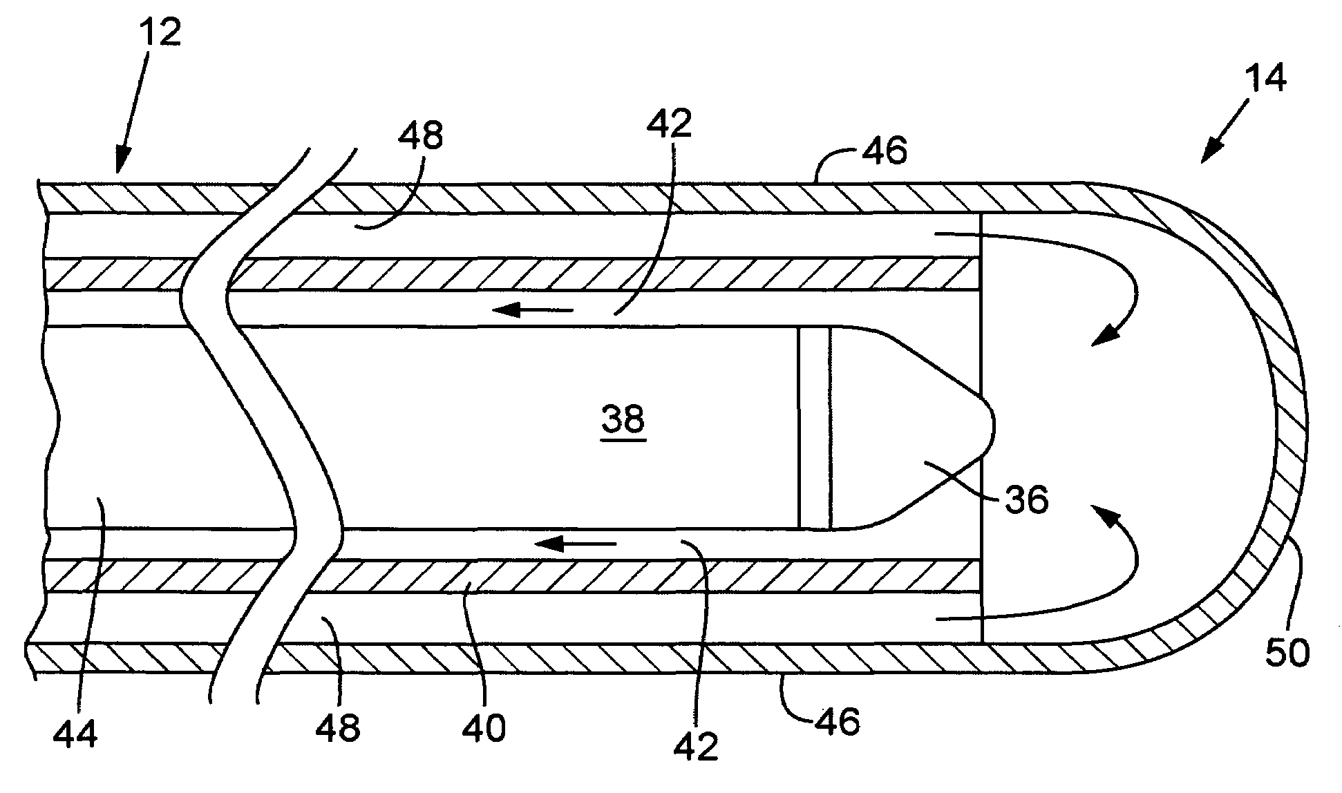
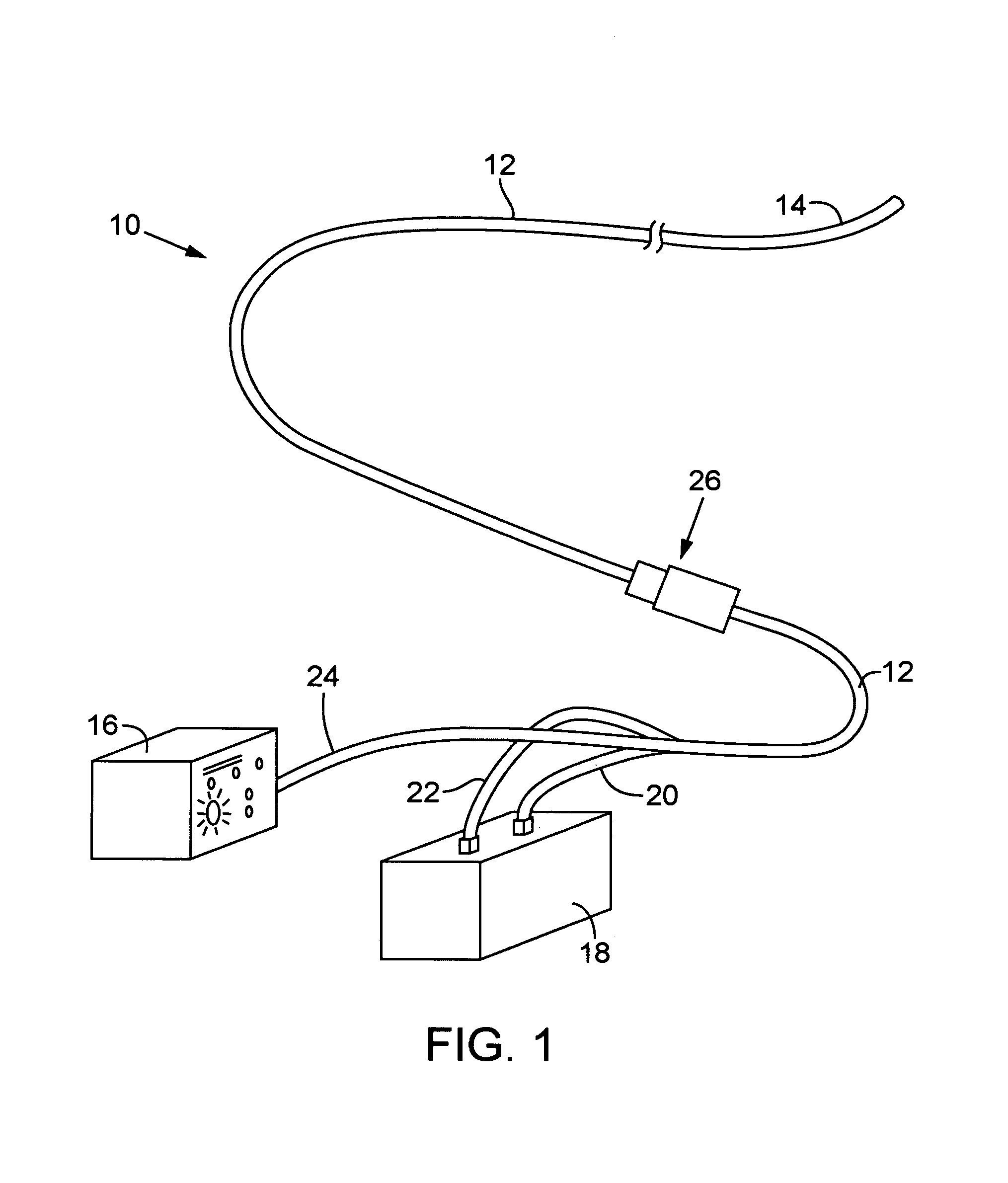
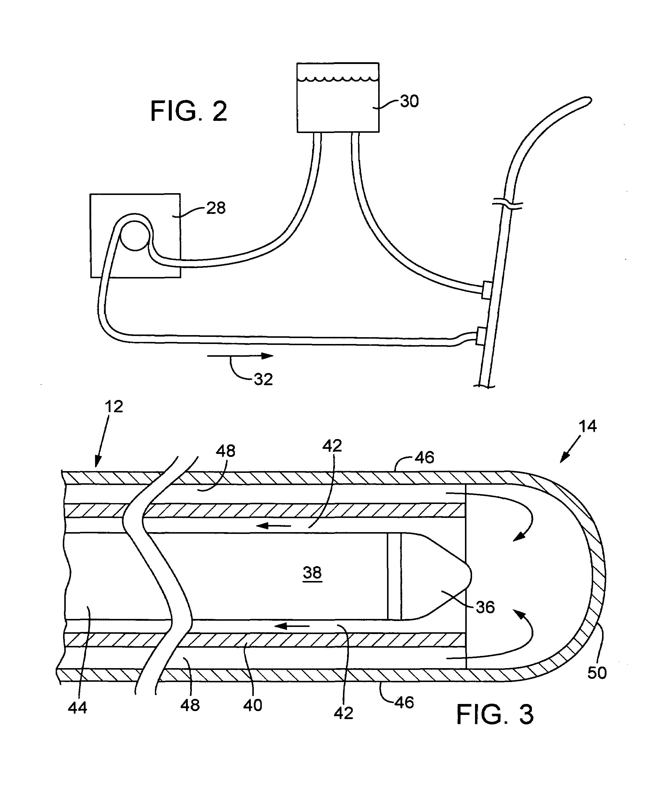
[0026]In the drawings, FIG. 1 shows a system 10 for administering x-ray treatment within a body cavity, channel or lumen via a catheter 12 having a distal end 14 containing a miniature, switchable x-ray tube, and including a controller 16 for the x-ray tube. The catheter 12 in a preferred embodiment is of small enough diameter to be used in blood vessels, mammary ducts and other small lumens of the body, and may have an external diameter on the order of about 0.5 mm to 4 mm. The apparatus 10 includes a cooling system for cooling the x-ray tube as it emits radiation within the body, including a coolant liquid reservoir 18 with a pump and other features described below. As indicated, coolant inflow and outflow or return tubes 20 and 22 connect to the reservoir 18 and into a portion of the catheter 12 near the proximal end 24. The high voltage cable from the controller 16 extends through the entire catheter 12, preferably joined by the coolant inflow and outflow 20, 22 at a position sp...


PUM


Abstract

A miniature x-ray tube is cooled using a catheter preferably having multiple small lumens for inflow and outflow of coolant. Inflow may be through an outer lumen(s) in a concentric-extrusion catheter, the liquid turning back at the distal end of the catheter to a proximal flow over the anode end of the x-ray tube and through an inner lumen within which the x-ray tube is positioned. A coolant distribution head may engage with the anode end of the x-ray tube, with small orifices so as to distribute coolant essentially evenly over the anode surface. Temperature and flow rate of the inflowing coolant liquid are balanced so as to optimize heat transfer while efficiently carrying coolant through small lumens without the need for high pressures. Some embodiments use the inflation liquid in an applicator balloon as the coolant, with the liquid actively flowing or, in a simplified system, with the liquid static.

Description

BACKGROUND OF THE INVENTION[0001]The invention concerns miniature x-ray tubes for therapeutic treatment of specific areas within the human body, such as a blood vessel, duct or other small lumen, and in particular the invention concerns cooling of such a miniature x-ray tube in an efficient manner without requiring an unduly large catheter to carry the coolant.[0002]Miniature or small x-ray tubes for human therapeutic treatment are discussed in several prior patents, including U.S. Pat. Nos. 5,854,822, 5,621,780 and 6,319,188. Such small x-ray tubes have been intended for treatment of tumors within surgical openings in the body, for treatment within blood vessels using a catheter containing the tube, and for other radiation treatments within the body. Cooling of miniature x-ray tubes, particularly when used within lumens of the body, is an important issue. One prior approach has been an open loop cooling system, wherein a liquid coolant (saline solution) is dumped into the blood flo...

Claims


Application Information

Patent Timeline
Patent Type & Authority Patents(United States)
IPC IPC(8): H01J35/32A61F2/958A61M25/00A61N5/00A61N5/10
CPCA61N5/1002H01J35/32H05G1/025A61M2025/0034A61M2025/0036A61M2025/0039A61N2005/005A61N2005/1022H01J2235/1216H01J2235/122H01J2235/1262A61M25/003A61M25/10A61M2025/0004
Inventor LOVOI, PAUL A.RIEKE, JOHNLIM, ALEXSMITH, PETER C.RUSCH, THOMAS W.
Owner XOFT MICROTUBE
Why Eureka
Try Eureka