[0021]In one aspect of the invention, a computer implemented process is provided for developing a
circuit design layout. Scan cells of a design are ordered according to a prescribed scan cell ordering rule. Physical placement involves placing cells according to weights assigned to scan cell ordering relationships in addition to circuit path connection relationships. Assigning different weights to both scan cell order relationships and circuit path connection relationships permits optimized placement of cells in both test mode and function mode while reducing timing
impact of scan ordering weighed placement upon functional mode operation.
[0022]In another aspect, a computer implemented process for designing integrated circuits is provided. The process makes use of information in a design
database and a timing database. A netlist including multiple scan cells is received from the design database. Source
clock trigger time (Source CTT) information is received from the timing database. Source CTT information indicates the occurrence times of source
clock edges. That is, the source CTT for a scan cell is the time at which a source
clock produces a clock edge that triggers the scan cell. In this context, clocks are treated as ideal clocks without considering
propagation delay to derive the source CTT values. The multiple scan cells are ordered relative to each other in descending time order of their triggering source CTTs. Ordering scan cells in descending CTT order can further reduce the risk of
hold time violations.
[0023]In another aspect of the invention, a computer implemented process for designing integrated circuits is provided. The process makes use of information in a design database and a timing database. A netlist including multiple scan cells is received from the design database. As explained above in connection with another aspect of the invention, source CTT represents CTT of an ideal source clock. However, in reality, there may be a
propagation delay time between a source CTT and the time when a corresponding triggering edge actually arrives at a scan cell triggered by that triggering edge. To take this propagation
delay into account, we introduce the concept of instance clock trigger time (Instance CTT). Instance CTT information is received from a timing database. Instance CTT information indicates arrival times of propagated triggering clock edges at scan cells that are triggered by such respective clock edges. That is, the instance CTT for a scan cell is the
arrival time of a triggering clock edge at the scan cell, where the triggering clock edge may experience propagation
delay as it propagates from a triggering source clock to a triggered scan cell. The multiple scan cells are ordered relative to each other in descending order of arrival times of their triggering clock edges (i.e., their instance CTTs). Ordering scan cells in descending instance CTT order can reduce the risk of
hold time violations.
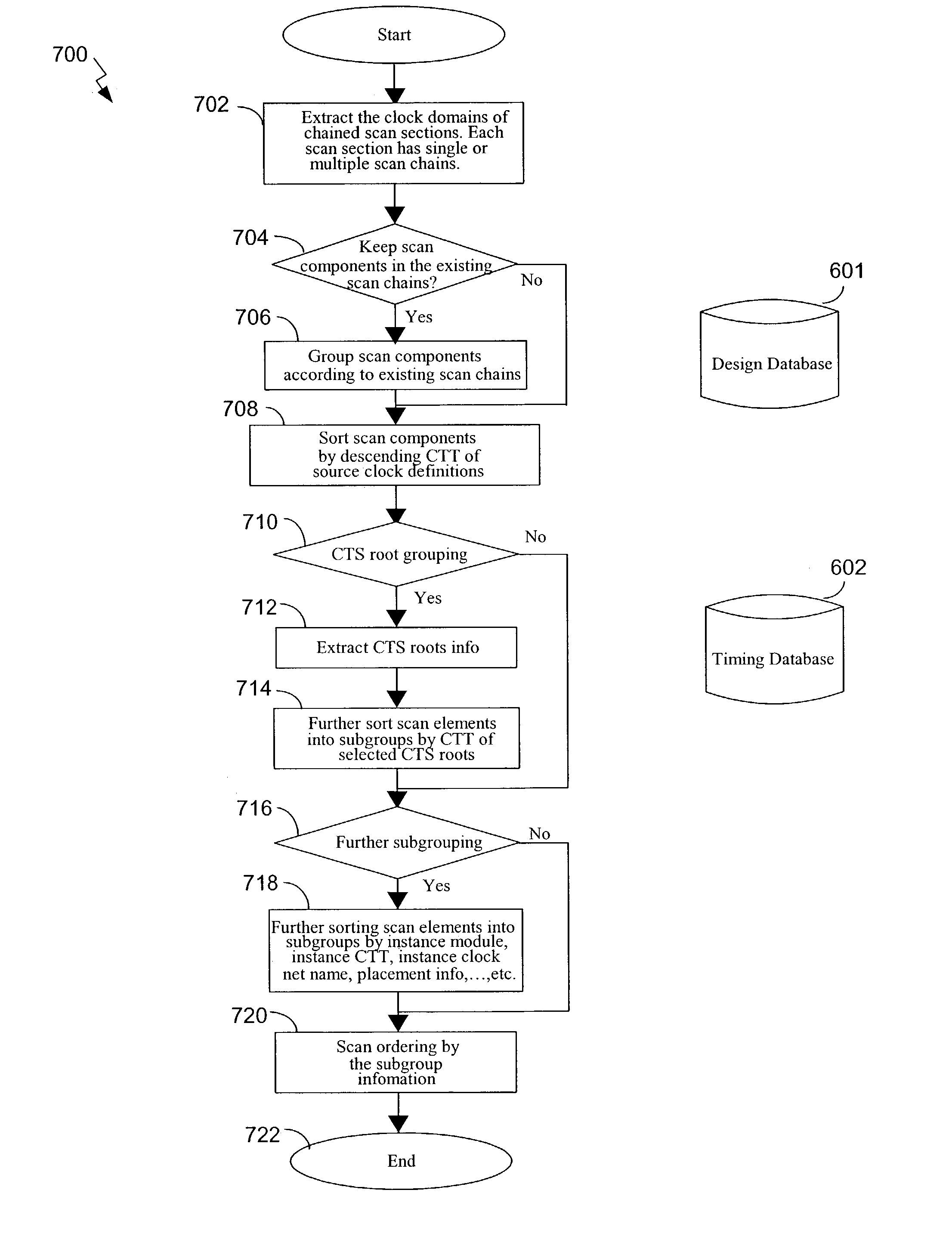
[0024]In yet another aspect of the invention, a computer implemented process for designing integrated circuits is provided. The process makes use of information in a design database and a timing database. A netlist is received from the design database. The netlist includes multiple respective scan cells triggered by respective triggering edges of one or more source clocks.
Clock timing information is retrieved from a timing database. The clock timing information includes timing information for one or more triggering clock edges.
Clock tree information is received from the timing database. The
clock tree information identifies source clock roots of each of the respective triggering clock edges. The scan cells are partitioned into subgroups based upon source clock roots of their respective triggering clock edges. Each subgroup contains only scan cells triggered by a clock edge from the same source clock root. Scan cells of different respective subgroups are triggered by clock edges from different source clock roots. Grouping scan cells based on
clock tree roots tends to reduce congestion because during (subsequent) placement, scan cells sharing a
clock tree root will tend to be placed nearer each other. An associated time value is specified for each subgroup. Each such associated time value is derived from triggering clock edge timing information of the scan cells within the subgroup having that associated subgroup time value. The subgroups are ordered relative to each other based upon their respective associated subgroup time values. In a present embodiment, the subgroups are ordered relative to each other in a descending order of their associated subgroup time values. In addition, scan cells within the subgroups can be ordered so as to further reduce overall wire length and congestion. Thus, there is an ordering of subgroups based upon subgroup instance CTT information, and there can be a further sub-ordering of scan cells within subgroups so as to reduce overall wire length and congestion. Ordering scan cell subgroups so as to reduce the risk of
hold time violations while ordering scan cells within subgroups based upon instance CTTs facilitates a balancing of a need to reduce the risk of
scan chain hold time violations with a need to reduce overall
scan chain wire length and congestion.

