Method for determining a surface contact force

a contact force and surface pressure technology, applied in the direction of force measurement by measuring optical property variation, instruments, machines/engines, etc., can solve the problems of slow response time, significant barrier, and significant distance between taps that require additional sophisticated interpolation procedures

Active Publication Date: 2006-10-31
INNOVATIVE SCI SOLUTIONS
View PDF13 Cites 35 Cited by
  • Summary
  • Abstract
  • Description
  • Claims
  • Application Information

AI Technical Summary

Problems solved by technology

Even then, the significant distance between taps usually requires additional sophisticated interpolation procedures.
Such a slow response time represents a significant barrier to utilizing PSPs for the investigation of transient fluid phenomena.
Unfortunately, this sensitivity can not be increased significantly due to both the physical and photochemical properties of available formulations.
Thus, it is very difficult to utilize PSP in applications with small pressure variations such as measurements at low subsonic velocities (Mach number (Ma) below 0.05).
Since the PSP sensitivity can not be modified to accurately cover this low scale, reliable results can generally only be obtained by increasing the signal to noise ratio of the acquired intensity (typically by averaging many images) and compensating for all possible error sources such as illumination non-stability, model displacement and deformation, and temperature effects.
A drawback of this method is the fact that gradients of the normal pressure can also create a shear displacement of the polymer gel and thus this method works best in the absence of normal pressure gradients.
This creates a difficult problem in determining shear deformation from normal and shear surface load components.

Method used


Image

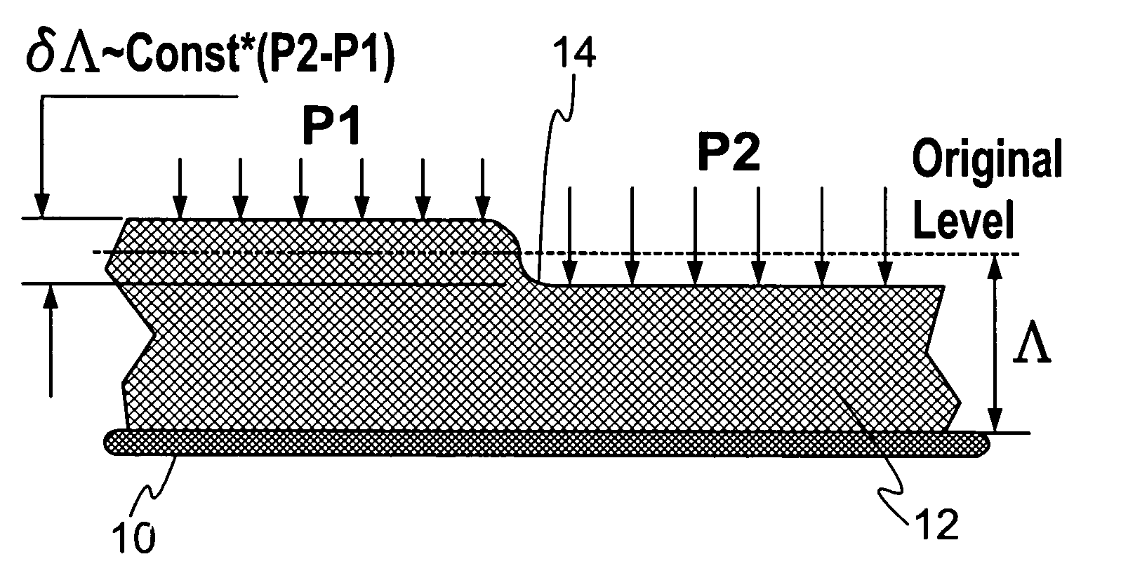
  • Method for determining a surface contact force
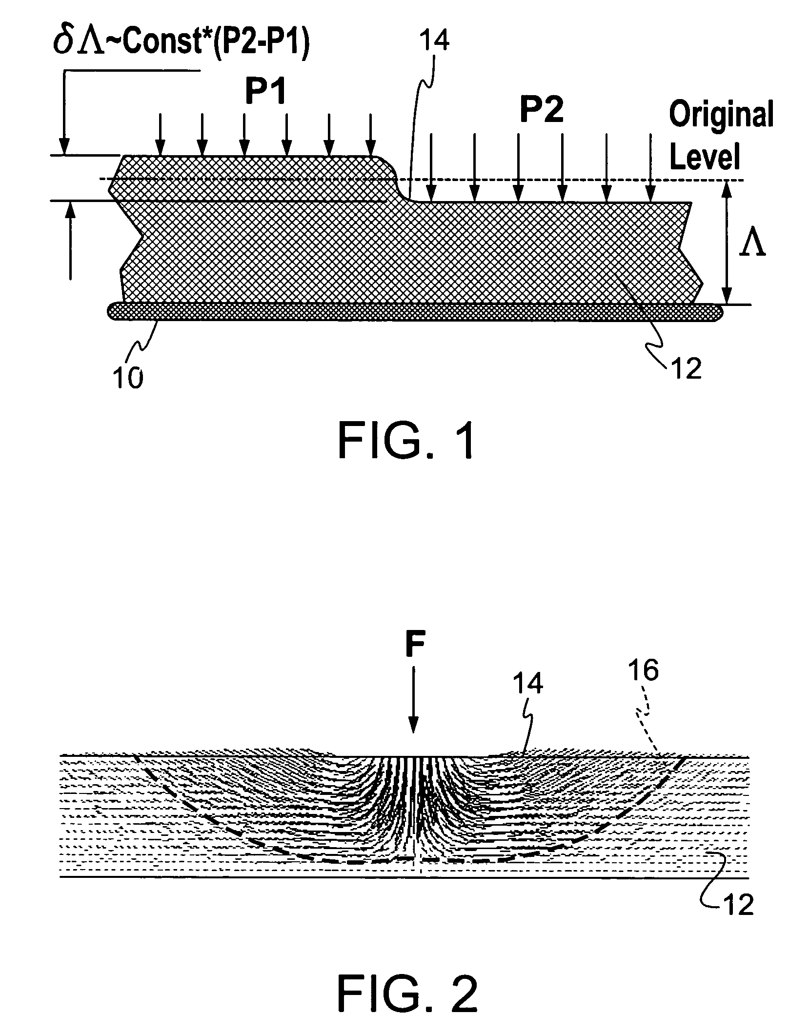
  • Method for determining a surface contact force
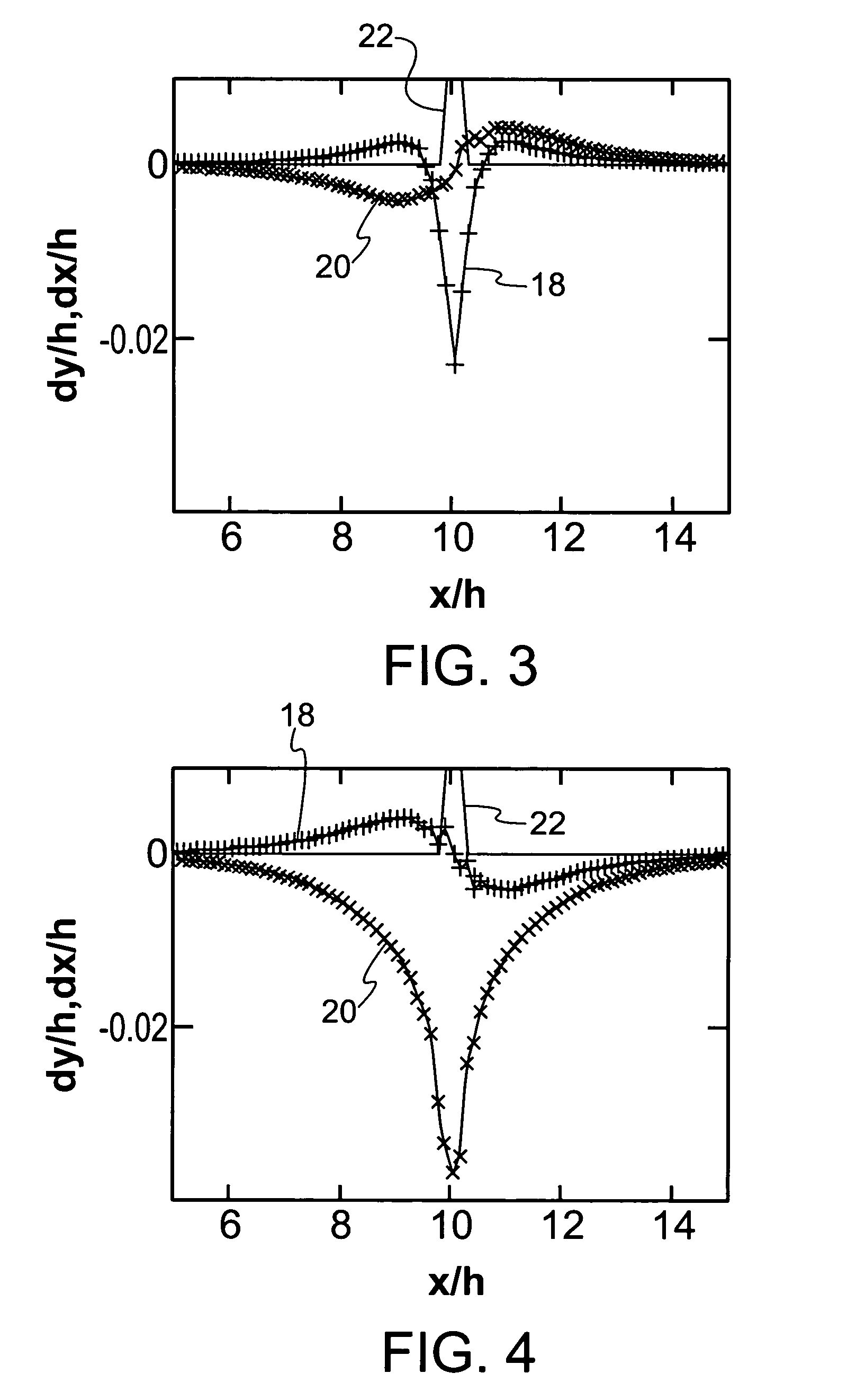
  • Method for determining a surface contact force

Examples


examples

[0071]Referring to FIG. 13, a delta wing model, defined by phantom line 36, was used to test the PSF technique at a flow velocity of 15 m / s and an angle of attack of 10°. The model surface was covered with a polymer layer having a thickness of 1 mm, where the film is positioned within a cavity of a depth substantially equal to the thickness of the film to position the upper surface of the film generally coplanar with the surrounding surface of the wing. A fine phosphor powder was applied on top of the PSF to create a pattern that could be used for shear deformation measurements.

[0072]FIG. 13 illustrates the result of a cross correlation analysis of the shear displacement field. It can be seen that the aerodynamic load produces a vortex region creating a narrow decompression region, generally depicted by 40, above the wing. The decompression region 40 produces a vertical component of the shear vector. The region 42 depicts a substantially greater vertical component of shear vector wi...


PUM

PropertyMeasurementUnit
thicknessaaaaaaaaaa
diameteraaaaaaaaaa
thicknessaaaaaaaaaa

Abstract

A method of measuring a load on a surface produced by a contact force. An elastic film or coating is located on a supporting surface to provide an indication of normal and tangential or shear forces applied to the surface. A thickness measurement, corresponding to a normal displacement, and a tangential displacement of the film, corresponding to a shear displacement, is obtained and input to a response function to reconstruct the normal and shear load components of the contact force on the surface. A differential thickness measurement of the film is detected by an optical method in which a luminescent output from a luminophore in the film is measured. A luminescent output from a reference luminophore located below the film is also measured to provide a measurement system independent of the illumination source used to produce the luminescent output.

Description

CROSS-REFERENCE TO RELATED APPLICATIONS[0001]This application claims the benefit of U.S. Provisional Application No. 60 / 517,513, filed Nov. 5, 2003, which is incorporated herein by reference.BACKGROUND OF THE INVENTION[0002]1. Field of the Invention[0003]The present invention relates generally to surface-pressure and shear-tension measurements and, more particularly, relates to surface-pressure and shear-tension measurements based on the deformation of an elastic film located in association with the surface of an object or model.[0004]2. Description of Prior Art[0005]Convenient, reliable and inexpensive methods for determining pressure maps of surfaces, particularly on aerodynamic objects, are currently under development. One known approach is to employ pressure taps which are drilled into the surface under study and connected via tubing to multiplexed pressure gages or pressure gage arrays. Hundreds of pressure taps are generally required to get a pressure distribution over an enti...

Claims


Application Information

Patent Timeline
Patent Type & Authority Patents(United States)
IPC IPC(8): G01L1/24G01B11/16G01LG01M9/06G01V1/28
CPCG01L1/24
Inventor FONOV, SERGEY D.JONES, E. GRANTCRAFTON, JIM W.
Owner INNOVATIVE SCI SOLUTIONS
Why Eureka
Try Eureka