Support system of a tabletop vise

a support system and tabletop technology, applied in the direction of positioning apparatus, metal-working machine components, manufacturing tools, etc., can solve the problems of reducing the work efficiency of the user, and reducing the footprint over the layer. , the effect of small footprin

Inactive Publication Date: 2006-10-31
PLILEY LARRY E
View PDF6 Cites 15 Cited by
  • Summary
  • Abstract
  • Description
  • Claims
  • Application Information

AI Technical Summary

Benefits of technology

[0019]According to a highly preferred embodiment of the invention, the first recessed area and the second recessed area are coextensive, with a portion of the second recessed area extending from the first recessed area. With this arrangement, a support base with a rather small footprint against the layer of high friction material that can still support the vise in both a horizontal and vertical position is created. It is desirable to reduce the footprint over the layer of high friction material in order to make full use of the well-known rule of frictional force: F=Nμ, where N is the normal force and μ is the coefficient of friction for the material. Thus, reduction of the size of the footprint increases the force per unit area of the material. Also, the close proximity and low plane of the working plane allows the user to lightly press down on the base with one hand to prevent sliding, while using the fingers of the same hand to steady the other hand that is being used to perform the work.
[0020]It is contemplated that the hollow base will be made from a single sheet of molded plastic material, molded as a single concave unit that incorporates the first recessed area and the second recessed area. It is preferred that the first recessed area and the second recessed area will extend from the upper surface towards the base panel. It has been discovered that this arrangement creates a particularly rigid structure that allows even distribution of the weight of the vise, and any forces exerted on items being held on the vise, to the layer of flexible high friction material, allowing the material to develop a particularly effective grip on whatever surface is being used to support the system.
[0021]It is contemplated that the flexible high friction material may be a rubbery or rubber-like polymer that provides a high friction coefficient to the vise. The flexibility may be imparted by using a foam material or simply using a highly flexible material, which may contain features, such as protrusions or recesses, that facilitates the flexing of the flexible high friction material and its contact with the tabletop.

Problems solved by technology

While this approach provides the steady support needed to allow the user of the vise to exert force on the work piece without having the vise move away from the force, it lacks versatility, convenience and flexibility, especially for light applications, such as train or airplane model building, soldering of electronic components, and crafts.
Still further, the fixed location of known mounting methods also forces the user to move around the vise and work piece.
This original iteration provided a convenient receptacle for work pieces, but was not designed for providing a steady support for a vise and thus not capable of resisting vise workload.
The base disclosed in my U.S. Pat. No. 6,640,666 proved to be very useful in storing the vise, but limited in its ability to provide the versatility and support needed while performing many common tasks, such as sawing, grinding, or pressing items together.
While, making the base from a solid, non-hollow, single piece construction would help reduce the flexing, this construction would be too heavy and expensive.
Additionally, the design disclosed in my above-referenced patent was limited in that it only allowed me to mount and / or hold the vise in a horizontal position, with the jaws opening upwards, as shown in that patent.
Still further, I often had to work on delicate, detailed items that required a very steady hand.
Known devices that had to be mounted from the protruding edge of the bench did not allow me to gain this support for my arms and hands from the bench.
Importantly, suction cups will not function properly on uneven or coarse surfaces.
The unevenness of these surfaces will prevent the suction cups from maintaining the proper vacuum, and thus will lose their grip on the surface.
The loss of vacuum by suction cups is a common problem even on smooth surfaces.
Dirt or any other foreign matter on the work surface will result in a loss of vacuum and a loss of grasp of the surface.

Method used


Image

  • Support system of a tabletop vise
  • Support system of a tabletop vise
  • Support system of a tabletop vise

Examples


Embodiment Construction

[0029]While the invention will be described and disclosed here in connection with certain preferred embodiments, the description is not intended to limit the invention to the specific embodiments shown and described here, but rather the invention is intended to cover all alternative embodiments and modifications that fall within the spirit and scope of the invention as defined by the claims included herein as well as any equivalents of the disclosed and claimed invention.

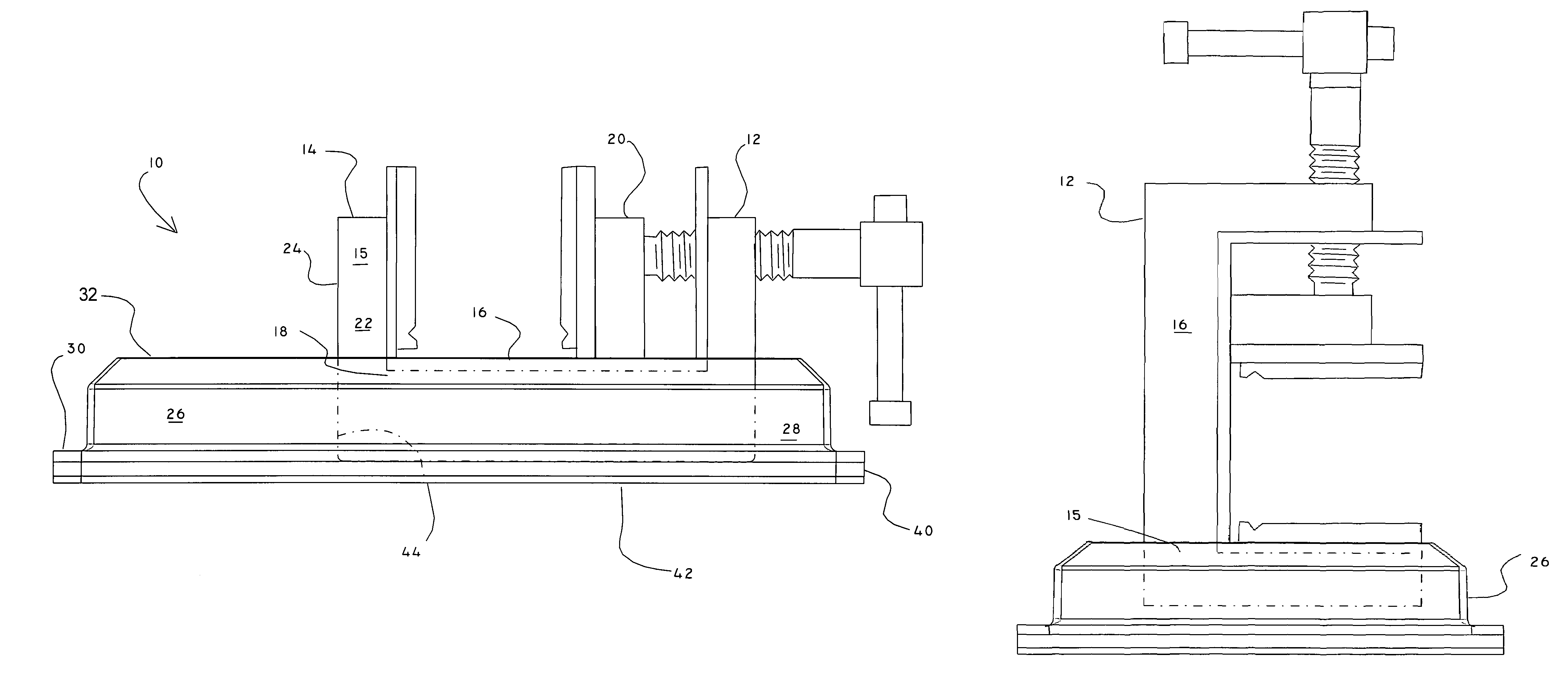
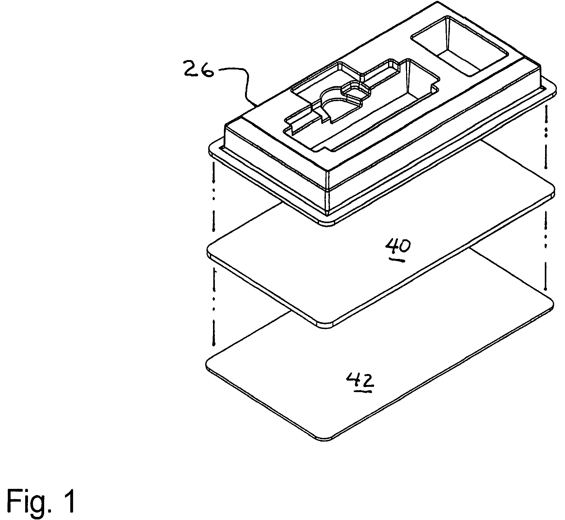
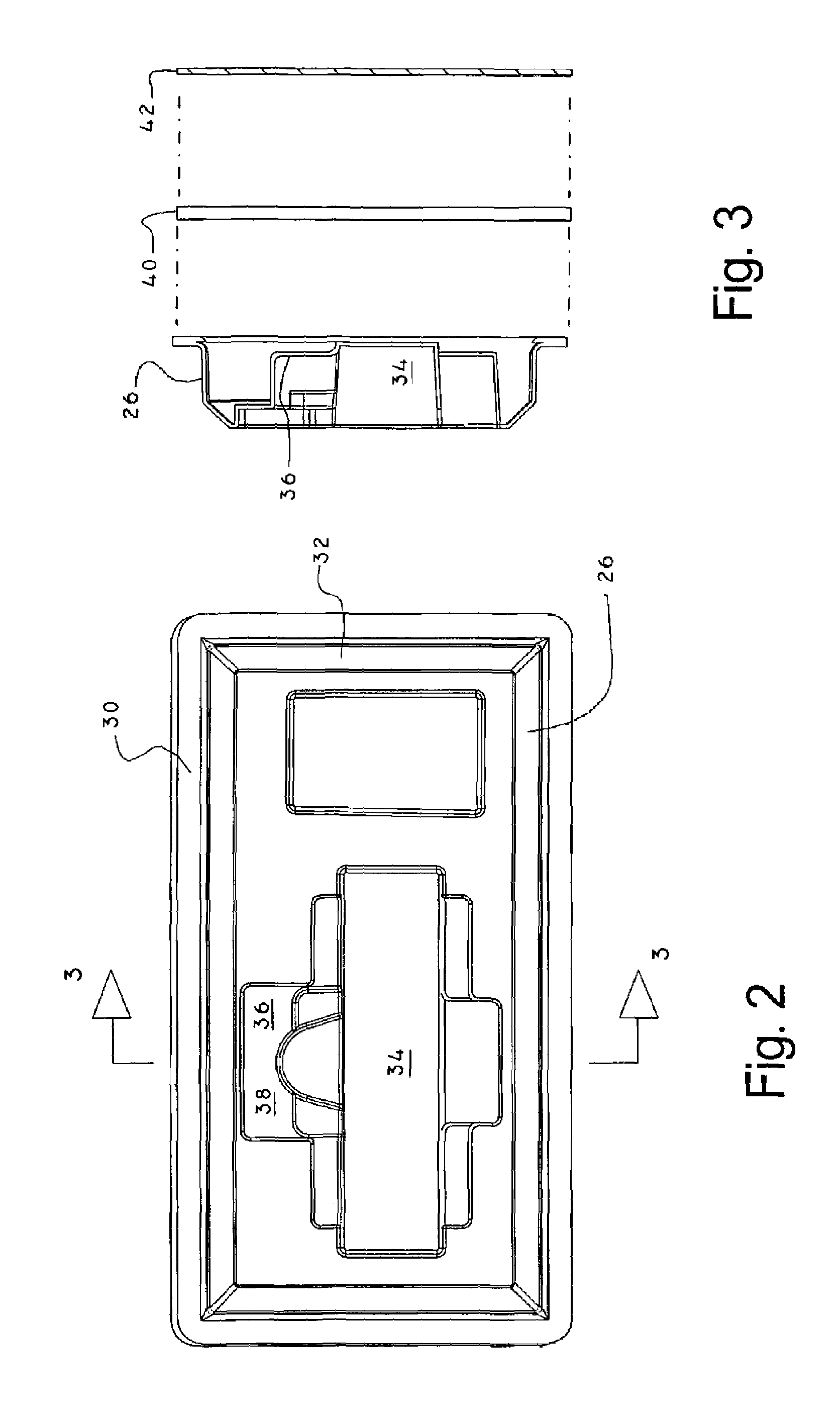
[0030]Turning now to FIGS. 1, 4 and 5 where a highly preferred example of a vise and base system 10 as disclosed herein has been illustrated. The vise 12, which is also disclosed in my U.S. Pat. No. 6,640,666, includes a stationary jaw 14. The stationary jaw 14 is mounted at fixed location on a frame 16. The frame 16 includes a frame perimeter wall 18, and also supports a moveable jaw 20. The moveable jaw 20 is moved along the frame 16 towards the stationary jaw 14 by way of a screw mechanism. As illustrated, the st...


PUM


Abstract

A vise and base system is disclosed. The vise includes a stationary jaw, a frame with a frame perimeter wall and a moveable jaw, the stationary jaw being fixed to the frame, and the moveable jaw that is movable along the frame. The vise cooperates with a hollow base that includes a first recessed area that is adapted for mating with the frame perimeter wall and a second recessed area that is adapted for mating with the stationary jaw. The base also includes a base panel that is attached to the base perimeter wall and a layer of flexible high friction material that is attached to the base panel, such that the base can support the vise in a generally horizontal position and in a generally vertical position.

Description

BACKGROUND OF THE INVENTION[0001](a) Field of the Invention[0002]This application relates to a system for supporting a vise while in use. More particularly, but not by way of limitation, to a system that includes a vise and a support base that supports the vise in an upright position as well as in a horizontal position.[0003](b) Discussion of Known Art[0004]In my U.S. Pat. No. 6,640,666, incorporated herein in its entirety by reference, I disclose a vise for securely holding a work piece such as a watch, delicate jewelry, or any other small, delicate item that needs to be solidly retained to allow work to be performed on the item. After working with the vise it became apparent that while the jaws and inserts use with my vise provide the needed secure grip of the work piece, there was a need for providing a sturdy support for the vise that was easy to use and would allow the use of the vise at any location on a variety of work surfaces.[0005]The typical approach at supporting a vise ...

Claims


Application Information

Patent Timeline
Patent Type & Authority Patents(United States)
IPC IPC(8): B23Q3/02
CPCB25B1/2484B25B5/006
Inventor PLILEY, LARRY E.
Owner PLILEY LARRY E
Why Eureka
Try Eureka