Secondary airflow system for engine exhaust emission diagnostics

a technology of exhaust emission and diagnostic system, applied in the direction of electrical control, process and machine control, instruments, etc., can solve the problems of affecting operation, reducing fuel economy, and affecting operation, so as to reduce or improve conditions, increase heat generation, and increase fuel economy

Active Publication Date: 2006-11-07
FORD GLOBAL TECH LLC
View PDF11 Cites 16 Cited by
  • Summary
  • Abstract
  • Description
  • Claims
  • Application Information

AI Technical Summary

Benefits of technology

[0006]In this way, it may be possible to provide a configuration that enables accurate air-fuel ratio control (since the total amount of airflow in the exhaust can be measured from the airflow sensor) while also providing accurate diagnostics. In one example, it is possible to accurately indicate inlet or outlet coupling degradation without requiring additional sensors in the secondary air system, such as an additional mass airflow sensor, or a pressure differential sensor measurement (although they could be added, if desired).
[0008]In this way, it may be possible to determine pump degradation based on whether a ratio of pump flow estimates is within a selected range to reduce the effect of estimation errors on diagnostic determinations. In other words, rather than simply considering whether absolute pump flow is outside an allowable range, it is possible to use a relative ratio of pump flows (such as after pump turn on and before pump turn off), thereby reducing the relative effect of estimation errors.
[0010]In this way, conditions may be reduced or avoided in which the benefits of increased heat generation during engine starting conditions may be outweighed by increased fuel economy and lost engine output.
[0011]An advantage of several of the above features is that it may be possible to isolate and distinguish between various types of degradation. This can be beneficial to determine which diagnostic codes to set and thereby indicate more precise diagnostic information to vehicle mechanics, for example.

Problems solved by technology

However, the inventors herein have recognized that when such a system is used in a configuration where the airflow is drawn from downstream of a mass airflow sensor, various types of degradation may occur.
As one example, inlet and outlet couplings can become loose or disconnected, thereby affecting operation.
In such a system, a disconnected inlet hose may produce an excessively lean air-fuel ratio.
Alternatively, a disconnected outlet hose may produce an excessively rich mixture.
In either case, the pump is still functioning yet operation may be degraded.
Further, in another example, even when pump hoses are functioning, pump degradation of the pump itself may occur.
There also may be engine operating conditions where even properly functioning elements may produce degraded operation.

Method used


Image

  • Secondary airflow system for engine exhaust emission diagnostics
  • Secondary airflow system for engine exhaust emission diagnostics
  • Secondary airflow system for engine exhaust emission diagnostics

Examples


Embodiment Construction

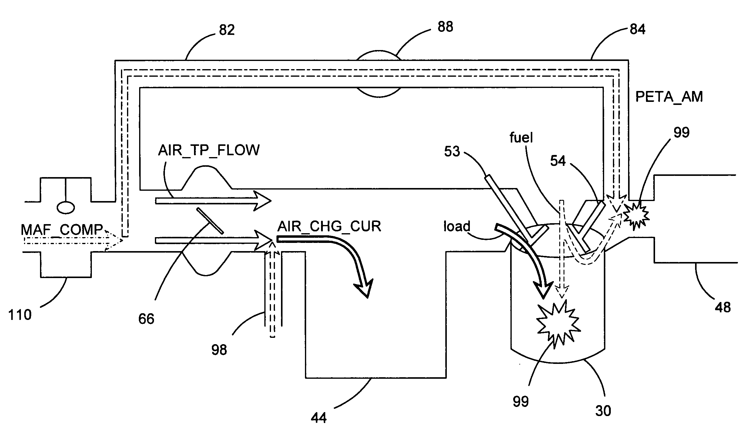
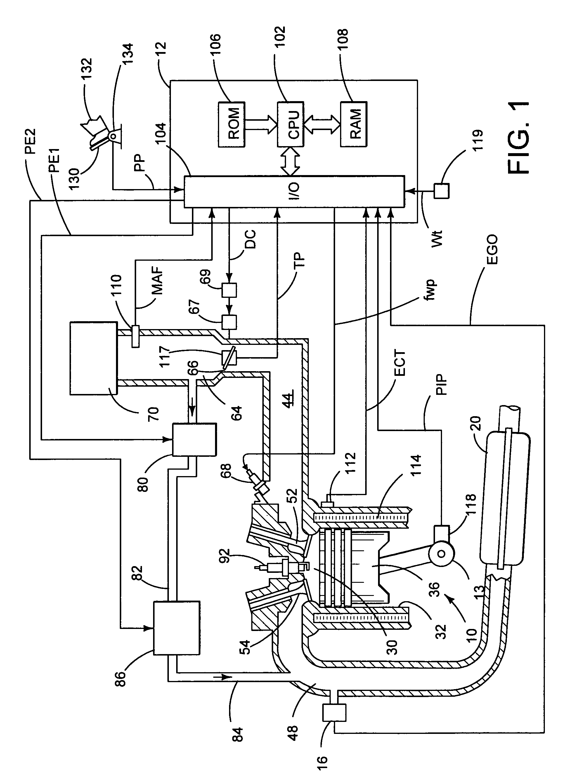
[0015]Internal combustion engine 10 comprising a plurality of cylinders, one cylinder of which is shown in FIG. 1, is controlled by electronic engine controller 12. Engine 10 includes combustion chamber 30 and cylinder walls 32 with piston 36 positioned therein and connected to crankshaft 13. Combustion chamber 30 communicates with intake manifold 44 and exhaust manifold 48 via respective intake valve 52 and exhaust valve 54. Exhaust gas oxygen sensor 16 is coupled to exhaust manifold 48 of engine 10 upstream of catalytic converter 20.

[0016]Intake manifold 44 communicates with throttle body 64 via throttle plate 66. Throttle plate 66 is controlled by electric motor 67, which receives a signal from ETC driver 69. ETC driver 69 receives control signal (DC) from controller 12. In one example, throttle plate 66 may be located in the intake system downstream of mass airflow sensor 110, which may be located downstream of air filter 70.

[0017]Intake manifold 44 is also shown having fuel inj...


PUM


Abstract

In one example, a system for an engine having an intake system and an exhaust system is described. The system comprises: an airflow sensor coupled to the intake system; an air pump having at least an inlet side and an outlet side, said inlet side having a first coupling to the intake system downstream of said airflow sensor, said outlet side having a second coupling to the exhaust system; and a controller coupled to the engine, said controller, during operation, identifying whether degradation has occurred to at least one of said first and second couplings, and providing an indication of said identified degradation. Various other examples are also disclosed.

Description

FIELD[0001]The field of the disclosure relates to a system for diagnosing secondary air introduction in an exhaust system of an internal combustion engine of a motor vehicle.BACKGROUND AND SUMMARY[0002]Engines take various approaches to increase exhaust temperature during an engine start to increase catalyst converter activity, and thereby reduce emissions. In one approach, such as in U.S. Pat. No. 6,640,539, airflow is pumped in to an engine exhaust manifold, while the cylinders are operated rich, to generate an exothermic reaction of rich gasses and oxygen.[0003]However, the inventors herein have recognized that when such a system is used in a configuration where the airflow is drawn from downstream of a mass airflow sensor, various types of degradation may occur. As one example, inlet and outlet couplings can become loose or disconnected, thereby affecting operation. In such a system, a disconnected inlet hose may produce an excessively lean air-fuel ratio. Alternatively, a disco...

Claims


Application Information

Patent Timeline
Patent Type & Authority Patents(United States)
IPC IPC(8): F01N3/00G01M99/00
CPCF01N3/22F01N3/32F01N11/00F02D41/185F01N2550/14F01N2560/07Y02T10/20Y02T10/47Y02T10/12Y02T10/40
Inventor SEALY, BRENTDOERING, JEFFCULLEN, MICHAELWRIGHT, DAVIDPIETRZYK, PAUL
Owner FORD GLOBAL TECH LLC
Why Eureka
Try Eureka