
Device and method for converting a balloon catheter into a cutting balloon catheter

a technology of cutting balloon and balloon catheter, which is applied in the field of intraluminal devices, can solve the problems of increasing the degree of vascular trauma, the catheter is not strong enough to sufficiently open such lesions, and the catheter is required to be larger

Inactive Publication Date: 2006-11-07
ANGIODYNAMICS INC
View PDF26 Cites 83 Cited by
  • Summary
  • Abstract
  • Description
  • Claims
  • Application Information

AI Technical Summary

Benefits of technology

The present invention provides a device for treating a lesion in a body lumen that can be easily inserted through a standard balloon catheter. The device includes a longitudinal housing with a wire that can be extended and retracted through an opening in the housing. The wire has a cutting edge that points toward the lumen wall when extended. The device can be used with various size balloon catheters and protects the vessel wall from accidental cutting during insertion and withdrawal. The technical effects of the invention include the ability to treat various size lesions with a single device and the elimination of the need for a separate cutting balloon catheter inventory.

Problems solved by technology

Some stenotic lesions can be highly resistant to opening at reasonable pressures and occasionally balloon catheters are not strong enough to sufficiently open such lesions.
Such a high pressure increases the degree of vascular trauma caused by the rapid stretching and tearing of the media and adventia layers of the vessel.
Typically these catheters require larger sheath sizes than low-pressure balloon catheters and are expensive due to the materials and design required to achieve high pressures.
The use of more than one wire will address this problem but it is difficult to control the positioning within the lesion of more than one guidewire.
Lack of control over guidewire location relative to the balloon makes the procedure more unpredictable and difficult than conventional angioplasty procedures.
Although cutting balloon technology addresses some of the problems associated with conventional angioplasty, there are several drawbacks with the use of cutting balloons.
Difficulties in advancing the balloon through the vasculature to the target lesion are more frequent with a cutting balloon than with a conventional angioplasty balloon of an equivalent inflation diameter due to the larger profile.
Insertion, advancement and placement of cutting balloons are also more difficult because the relatively stiff blade materials prevent the cutting balloon from being as flexible as standard angioplasty catheters.
Accordingly, tracking the device through tortuous vasculature is more problematic with the cutting balloon.
While the keyhole design increases the overall flexibility of the cutting balloon, it adds complexity to the micro-precision manufacturing process and costs.
Again, while increasing flexibility, the design adds complexity to the manufacturing cost and still does not address the problems associated with increased overall device diameter.
Prior art cutting balloons are also disadvantageous during withdrawal of the device.
While Vigil provides an increased level of protection during withdrawal, there are still disadvantages with the Vigil design.
The balloon deflation process is not always controllable and the deflated balloon surface does not always adequately cover the blades.
Furthermore, deflation failures, common with angioplasty balloons, may result in significant patient complications when the cutting balloon fails to completely deflate.
Balloon rupture and other mechanical failure may result in the necessity of surgically retrieving blade components from the vessel.
Another disadvantage of cutting balloons is cost.
This becomes very expensive and requires a large inventory space.
Although Barath's device allows customization of a standard angioplasty balloon for a variety of procedures and thus reduces inventory requirements, it does have several deficiencies.
The concentrator increases the overall profile of the device resulting in insertion and advancement complications as previously discussed.
Even after deflation in its reduced profile, the atherotomes or blades remain exposed and may thus increase the possibility of unintentional incision of non-target vessel segments during withdrawal.
Another disadvantage of Barath's concentrator design relates to balloon inventory-stocking levels.
Although Barath's design reduces the inventory requirements for angioplasty procedures, each balloon length would require a separate concentrator length thus introducing complexity and additional inventory parts into the angiosuite.
In addition, the difference in balloon specifications among manufacturers makes custom fitting of the concentrator to the balloon difficult.
Still another disadvantage of cutting balloons is that a physician is required to remove the standard angioplasty catheter already in the vessel and insert in its place the cutting balloon catheter.
With either approach, the balloon exchanges carry added risk, add time to the procedure, and increase treatment costs due to additional device use.
As persons of ordinary skill in the art can appreciate, this procedure carries substantial added risk to the patient, not to mention the increased cost and added procedure time.

Method used


Image

  • Device and method for converting a balloon catheter into a cutting balloon catheter
  • Device and method for converting a balloon catheter into a cutting balloon catheter
  • Device and method for converting a balloon catheter into a cutting balloon catheter

Examples


Embodiment Construction

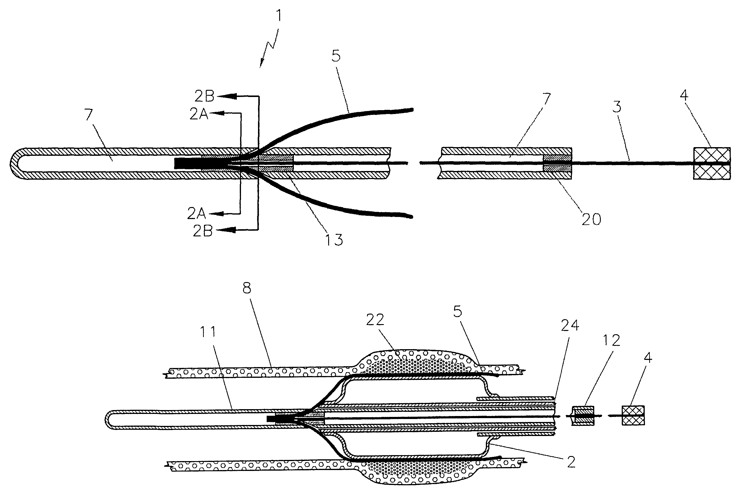
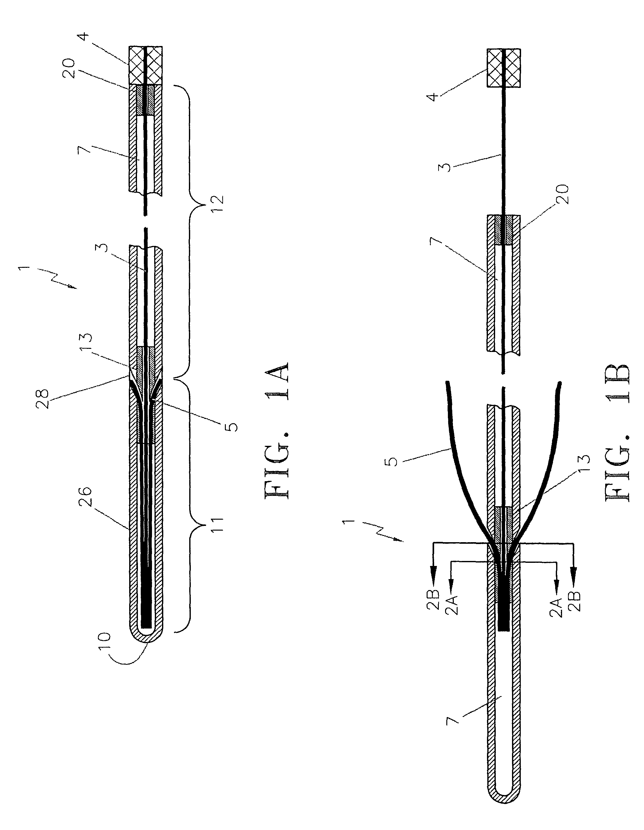
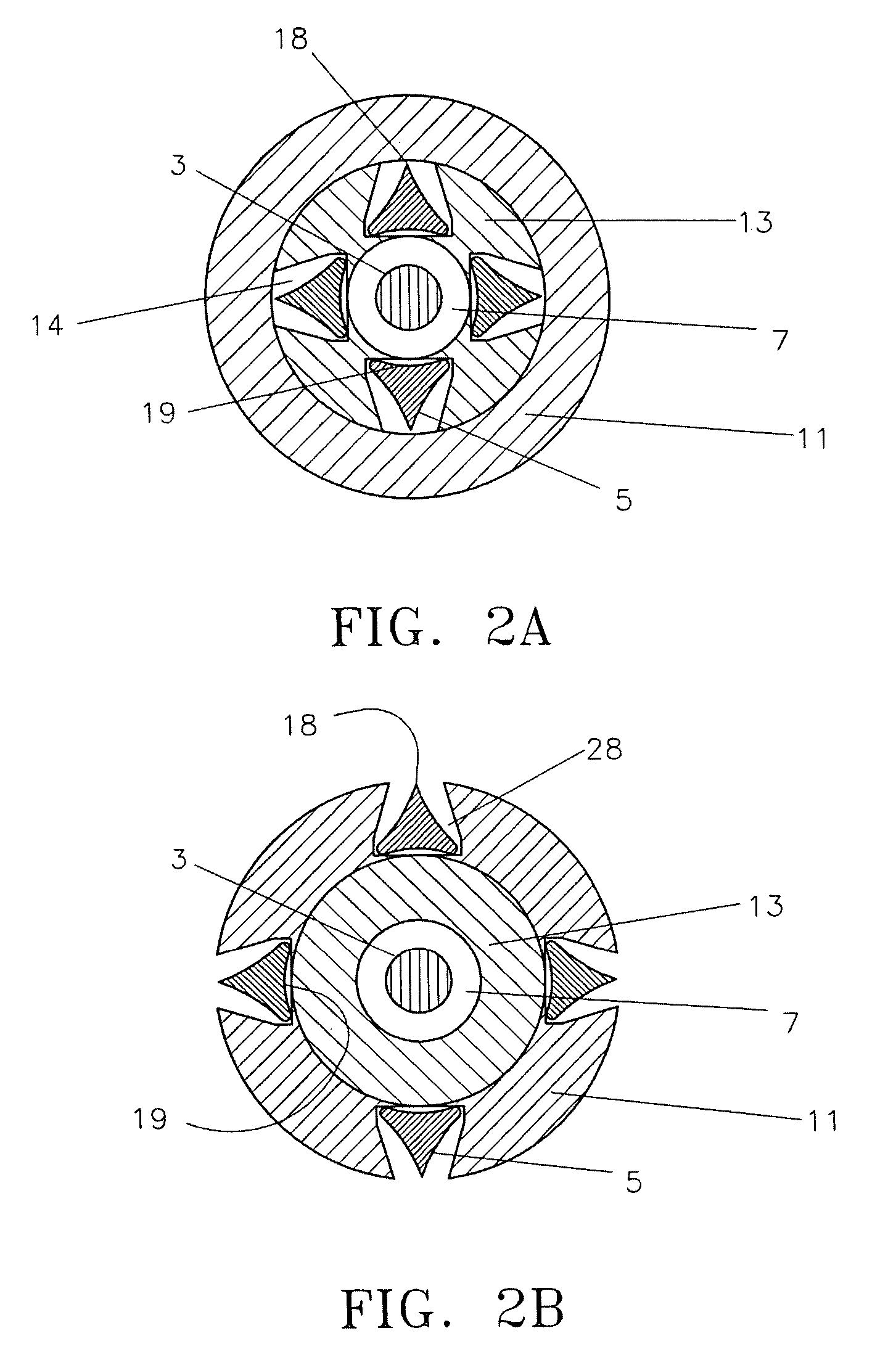
[0050]Referring to FIG. 1A, a conversion device 1 of the present invention is shown from a sectional view. Longitudinal housing 26 is preferably made from polymide shaft tubing or other flexible material with sufficient pushbability to navigate tortuous vessel channels. The outer diameter of the tube 26 is dimensioned so as to allow insertion of the device 1 within the guidewire lumen of a standard angioplasty catheter 24 (see FIG. 8). Typically, coronary balloon catheters accept 0.014″–0.018″ diameter guidewires. Balloon catheters for peripheral vascular applications accept 0.035″ diameter guidewires. For such a balloon catheter, therefore, the outer diameter of the longitudinal housing 26 is 0.035″ or lower. Because the conversion device 1 is delivered through the lumen of a standard angioplasty catheter, the problem with large profiles of prior art cutting balloons and the difficulty in insertion and advancement caused by the larger devices is completely eliminated.

[0051]The long...


PUM


Abstract

A lesion treating device for converting a standard balloon catheter into a cutting balloon catheter is provided. The device includes a longitudinal housing such as a tube which is sized to be inserted into a lumen of the balloon catheter and cutting wires disposed within the longitudinal housing in an undeployed position. When the longitudinal housing is moved relative to the cutting wires, the cutting wires extend out of the longitudinal housing. The balloon of the balloon catheter is then moved under the deployed cutting wires and inflated to convert the standard balloon catheter into the cutting balloon catheter.

Description

CROSS-REFERENCE TO RELATED APPLICATIONS[0001]This application claims priority to U.S. Provisional Application No. 60 / 457,458, filed Mar. 25, 2003, which is incorporated herein by reference.FIELD OF THE INVENTION[0002]The present invention relates to an intraluminal device, and more particularly to a device for converting a balloon catheter into a cutting balloon catheter.BACKGROUND OF THE INVENTION[0003]Treatment of stenosis by angioplasty balloon catheters is well known. Typically a lesion can be opened by a standard balloon catheter quickly and easily at moderate inflation pressures. Some stenotic lesions can be highly resistant to opening at reasonable pressures and occasionally balloon catheters are not strong enough to sufficiently open such lesions. For example, when treating a stenosis that occurs at the venous anastomosis of a dialysis graft, it is found that often these lesions require pressure in excess of 28 atmospheres. Such a high pressure increases the degree of vascul...

Claims


Application Information

Patent Timeline
Patent Type & Authority Patents(United States)
IPC IPC(8): A61B17/22A61M29/00
CPCA61B17/320725A61B17/32075
Inventor APPLING, WILLIAM M.SCHUR, ISRAELDI PALMA, GIORGIO
Owner ANGIODYNAMICS INC
Learn More