High rep-rate laser with improved electrodes

a laser and electrode technology, applied in the field of high-reprate lasers with improved electrodes, can solve the problems of substantial limited fluorine ion sputtering on the metal surface of the anode, and achieve the effects of reducing the height of the anode, and reducing the number of fluorine ions

Inactive Publication Date: 2006-11-07
CYMER INC
View PDF26 Cites 5 Cited by
  • Summary
  • Abstract
  • Description
  • Claims
  • Application Information

AI Technical Summary

Benefits of technology

[0010]Applicants' tests have shown that the porous insulating layer that covers substantially all of the discharge surface of the anode does not significantly interfere with the electric field between the electrodes and helps control the shape of the discharge making it more spatially uniform over chamber life, as compared to prior art anode designs. This increase uniformity in discharge shape results in greatly improved laser pulse quality over chamber life. Better discharge shape also minimizes the adverse effect of acoustic disturbances within the chamber resulting from reflected acoustic waves from one pulse reflecting back into the discharge region during the immediately following pulse. Embodiments of the present invention provide decreased burn-in times extended operating lifetimes and improved laser beam quality and beam stability.

Problems solved by technology

However, fluorine ion sputtering on the metal surface of the anode is substantially limited after the insulating layer has developed.

Method used


Image

  • High rep-rate laser with improved electrodes
  • High rep-rate laser with improved electrodes
  • High rep-rate laser with improved electrodes

Examples


first preferred embodiment

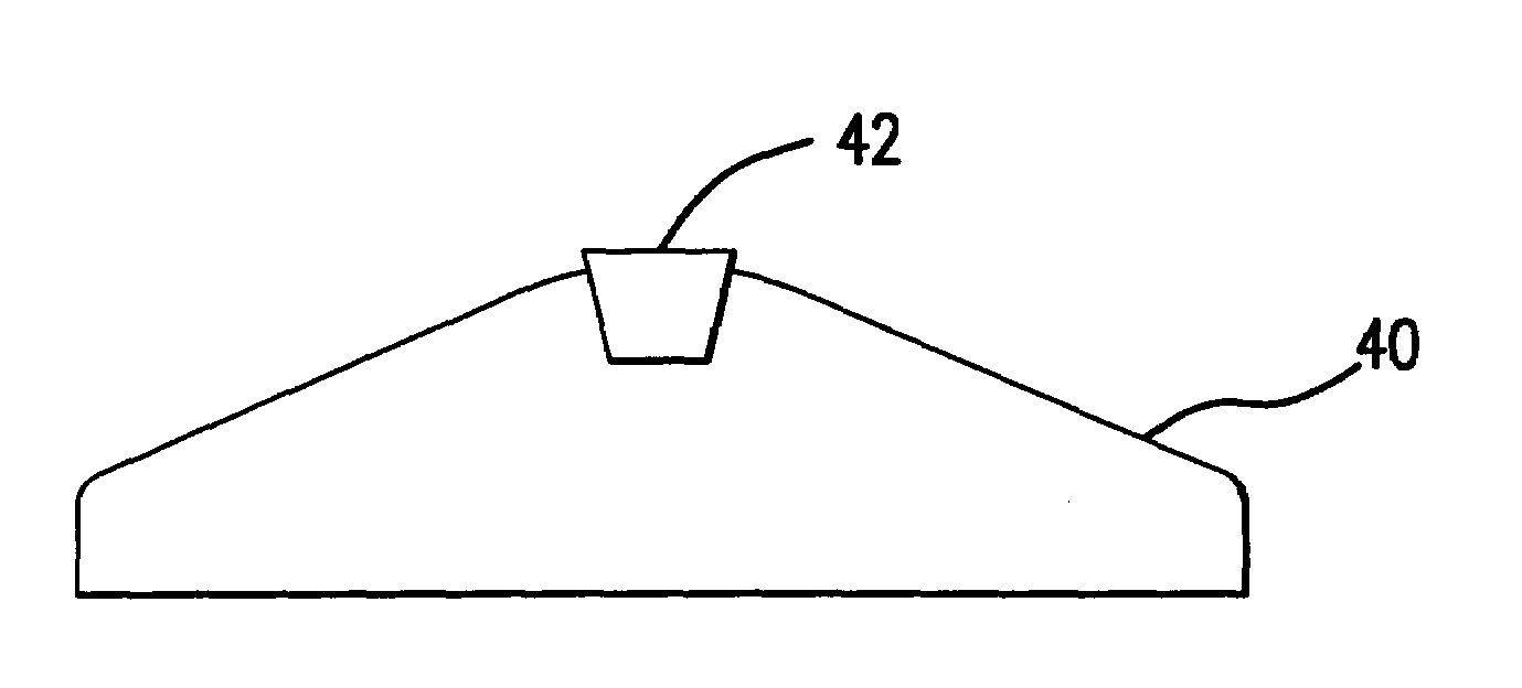
[0045]A first preferred embodiment of the present invention is a gas discharge laser such as KrF, ArF or F2 having an elongated anode with the cross section shown in FIG. 6. The anode is comprised of two types of brass, the main body 40 of the anode 83 in C26000 brass (having a lead content of less than 1%) which is 600 mm long. This anode is a modified version of a prior art anode which has been used extensively in these gas discharge lasers. The prior art 83 anode has a cross section as shown in FIG. 5. The width at the bottom is 1.2 inches. The height to the center tip is 0.380 inch. The tip has a radius of 0.5 inch. The shoulder height from the bottom surface is 0.13 inch. The slanted sides are flat planes at an angle of 27.67 degrees with the bottom surface. Applicants have proven with many laser-years of operation that this general anode shape produces excellent electric field properties and excellent discharge performance along with very good laser gas flow compatibility. In ...

second preferred embodiment

[0052]In a second-preferred embodiment of the present invention the anode is as described above and the cathode is similarly comprised of two materials, the first cathode material having a low cathode erosion rate positioned at the desired cathode discharge region and a second cathode material having a relatively higher cathode erosion rate positioned along two long sides of the first cathode material. Applicants have determined through several years of experimenting with brass electrodes that C36000 brass erodes about twice as fast as C26000 brass when used as cathode electrodes in fluorine containing gas discharge lasers. Cross sections of the cathode and anode in this embodiment are shown in FIGS. 7C and 7D respectively. This compares with the single material cathode and anode designs shown in FIGS. 7A and 7B which have been initialized previously in laser chambers designed and built by applicants and their fellow workers.

[0053]In the cathode the first material 90 located at the ...


PUM

PropertyMeasurementUnit
widthaaaaaaaaaa
widthaaaaaaaaaa
widthaaaaaaaaaa

Abstract

The present invention provides a gas discharge laser having at least one long-life elongated electrode for producing at least 12 billion high voltage electric discharges in a fluorine containing laser gas. In a preferred embodiment at least one of the electrodes is comprised of a first material having a relatively low anode erosion rate and a second anode material having a relatively higher anode erosion rate. The first anode material is positioned at a desired anode discharge region of the electrode. The second anode material is located adjacent to the first anode material along at least two long sides of the first material. During operation of the laser erosion occurs on both materials but the higher erosion rate of the second material assures that any tendency of the discharge to spread onto the second material will quickly erode away the second material enough to stop the spread of the discharge. In a preferred embodiment the anode is as described above and the cathode is also a two-material electrode with the first material at the discharge region being C26000 brass and the second material being C36000 brass. A pulse power system provides electrical pulses at rates of at least 1 KHz. A blower circulates laser gas between the electrodes at speeds of at least 5 m / s and a heat exchanger is provided to remove heat produced by the blower and the discharges.

Description

[0001]This application is a divisional of U.S. Ser. No. 10 / 104,502 filed Mar. 22, 2002 now U.S. Pat. No. 6,690,706 which is a continuation-in-part of U.S. Ser. No. 10 / 081,589 filed Feb. 21, 2002 now abandoned; U.S. Ser. No. 09 / 953,026 filed Sep. 13, 2001 now U.S. Pat. No. 6,711,202, U.S. Ser. No. 09 / 776,044 filed Feb. 1, 2001, which issued issued on Jun. 24, 2003 as U.S. Pat. No. 6,584,132; U.S. Ser. No. 09 / 768,753 filed Jan. 23, 2001, which issued on Jul. 2, 2002 as U.S. Pat. No. 6,414,979; U.S. Ser. No. 09 / 742,485 filed Dec. 20, 2000, now abandoned; U.S. Ser. No. 09 / 703,697, filed Nov. 1, 2000, which issued on Mar. 26, 2002 as U.S. Pat. No. 6,363,094; U.S. Ser. No. 09 / 590,961, filed Jun. 9, 2000, which issued on Oct. 15, 2002 as U.S. Pat. No. 6,466,602; Ser. No. 09 / 590,958, filed Jun. 9, 2000, which issued on May 6, 2003 as U.S. Pat. No 6,560,263; all of which are incorporated by reference herein.BACKGROUND OF THE INVENTIONThe KrF Excimer Laser[0002]The principal components of a p...

Claims


Application Information

Patent Timeline
Patent Type & Authority Patents(United States)
IPC IPC(8): B05D5/12B05D3/02G03F7/20H01S3/036H01S3/038H01S3/041H01S3/097H01S3/0979H01S3/22H01S3/223H01S3/225
CPCG03F7/70025G03F7/70041G03F7/70575G03F7/70933H01S3/036H01S3/038H01S3/0385H01S3/223H01S3/225H01S3/0381H01S3/0382H01S3/0387H01S3/0388H01S3/041H01S3/097H01S3/09702H01S3/0979H01S3/22H01S3/2207
Inventor MORTON, RICHARD G.DYER, TIMOTHY S.STEIGER, THOMAS D.UJAZDOWSKI, RICHARD C.WATSON, TOM A.MOOSMAN, BRYANIVASCHENKO, ALEX P.GILLESPIE, WALTERRETTIG, CURTIS
Owner CYMER INC
Why Eureka
Try Eureka