Method for varying the power consumption of capacitive loads

a technology of capacitive load and control circuit, which is applied in the direction of ac-dc conversion, electric variable regulation, sustainable buildings, etc., can solve the problems of instabilities of capacitive load such as compact fluorescent lamps, and achieve positive influence on the overall life of the lamp, prevent overvoltage, and reduce disruptive effects

Active Publication Date: 2006-11-07
ABL IP HLDG
View PDF2 Cites 27 Cited by
  • Summary
  • Abstract
  • Description
  • Claims
  • Application Information

AI Technical Summary

Benefits of technology

[0012]In addition, the circuit can evaluate a signal of the system power supply and produce a control signal on the basis of this signal which controls the power consumption of the load. This makes it possible to match the load operation to the variable system power supply.
[0013]In the present invention, the preferred form of the converter is a step-up converter. The current path in the circuit is preferably formed by a transistor which can be controlled by the control element. The step-up converter operates according to the invention once the system power supply has been applied to the load until the voltage across the smoothing capacitor of the load reaches a predetermined maximum value. This makes it possible to prevent overvoltages across the smoothing capacitor of the load, and for the life of the lamp overall to be positively influenced. In order to further reduce disruptive effects (for example the inductor of the dimmer), provision is made for the inputs of the load to be short-circuited upstream of the converter, thus bypassing the converter. This takes place according to the invention by means of an interface circuit which is connected between the rectifier and the converter and which produces a short circuit as long as no power is being supplied to the load on the system side. The interface circuit is in this case preferably decoupled from the converter by means of a decoupling diode such that no discharge processes can take place via the interface circuit, starting from the converter.

Problems solved by technology

When the system power supply is not constant, such as during dimming, for example, capacitive loads such as compact fluorescent lamps are susceptible to instabilities which appear in the form of disruptive flickering in the case of lamp operation.

Method used


Image

  • Method for varying the power consumption of capacitive loads
  • Method for varying the power consumption of capacitive loads
  • Method for varying the power consumption of capacitive loads

Examples


Embodiment Construction

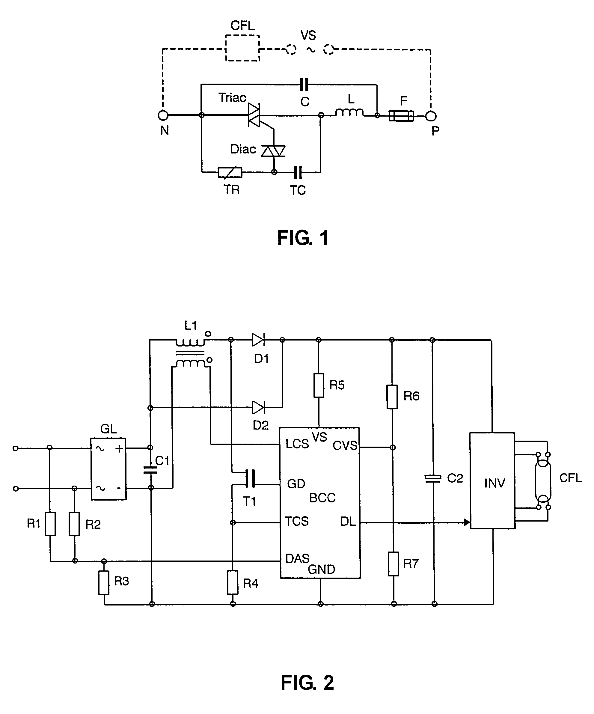
[0023]FIG. 1 shows an example of the circuit arrangement for the operation of a load using a phase-gating dimmer. Shown is a circuit in which a load CFL is operated by an AC voltage / system power supply VS. The load CFL is supplied with power by this voltage source VS via a phase-gating dimmer (between the points N and P). Phase-gating dimmers provide a periodic system power supply to the load which is isolated in each half-period, with a time delay, by tripping a power breaker triac by means of a variable timing element diac, TR, TC. In addition to the power breaker triac and the timing element, which is formed from a diac, a capacitor TC and a variable resistor TR, there are generally further provided in the dimmer circuit a fuse F and, for radio interference suppression, also a capacitor C and an inductor L.

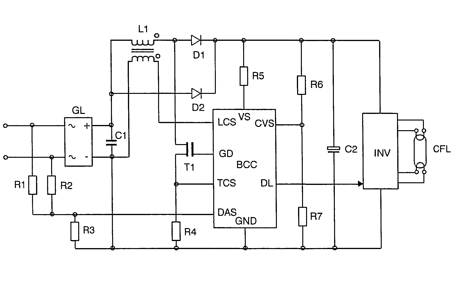
[0024]The method according to the invention is based on the arrangement in terms of circuitry of a step-up converter which is formed in FIG. 2 as part of the integrated ballast...


PUM


Abstract

Method for varying the power consumption of capacitive loads, in particular compact fluorescent lamps which are operated using a phase-gating dimmer by a converter (step-up converter). According to the invention, in the case of a nonconducting dimmer (i.e. no system power supply to the load), the switch (T1) in the converter (step-up converter) is closed. In the case of a conducting dimmer (i.e. when a system voltage is applied to the load), the step-up converter operation takes place until a predetermined maximum voltage is reached across the smoothing capacitor of the load.

Description

TECHNICAL FIELD[0001]The invention relates to a method and a control circuit for varying the power consumption of capacitive loads, which are operated on the AC voltage power supply system by connecting and disconnecting, at the system frequency, the system power supply in each system half-cycle, and in particular to a ballast for a lamp.BACKGROUND ART[0002]Lamps such as discharge lamps, in particular compact fluorescent lamps (CFL), are usually operated on the power supply system by means of a rectifier circuit for rectifying an AC voltage supply and charging a capacitor, which is often referred to as a smoothing capacitor. The term lamp used here relates in particular to the compact fluorescent lamps mentioned, but may also be understood to mean other lamps such as halogen lamps. The DC voltage present across the capacitor serves the purpose of supplying power to an inverter, which operates the compact fluorescent lamp. The invention generally relates to varying the power consumpt...

Claims


Application Information

Patent Timeline
Patent Type & Authority Patents(United States)
IPC IPC(8): H05B37/00H02M7/12H05B41/24H02M7/217H03K17/725H05B41/285H05B41/36H05B41/392
CPCH02M7/217H05B41/2853H05B41/3924Y02B20/19Y02B20/00H05B41/36
Inventor FISCHER, KLAUSKREITTMAYR, JOSEF
Owner ABL IP HLDG
Why Eureka
Try Eureka